
Framing – Inner Wall
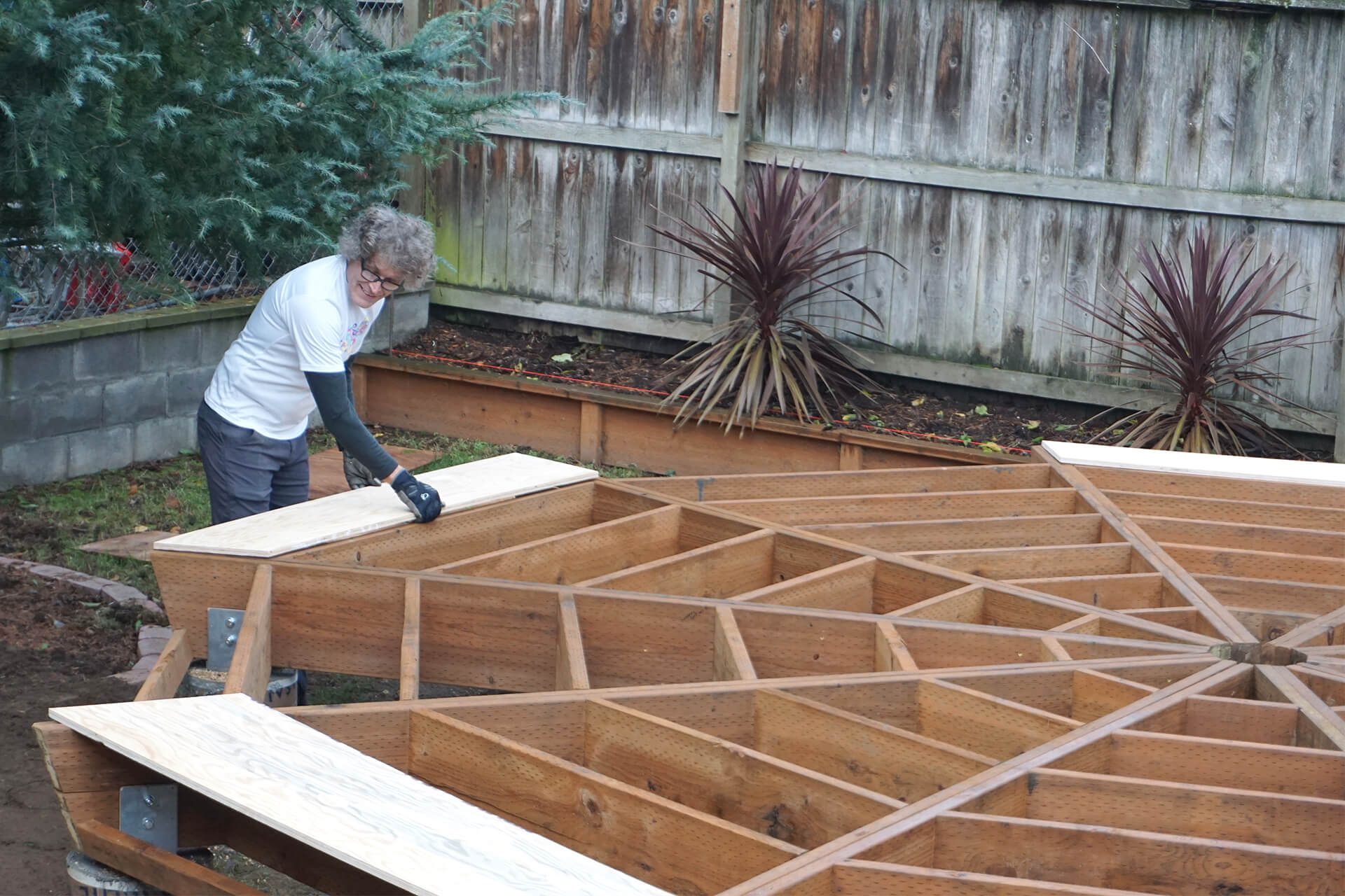
Lay out the Subfloor-C panels.
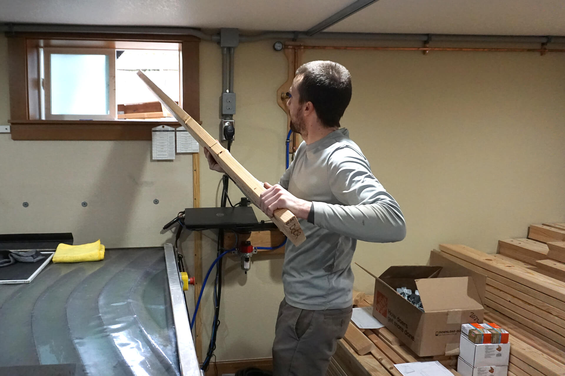
Gather the Sill-Plate-Ins. Bonus points for locating the prefabricated stack close to a window.
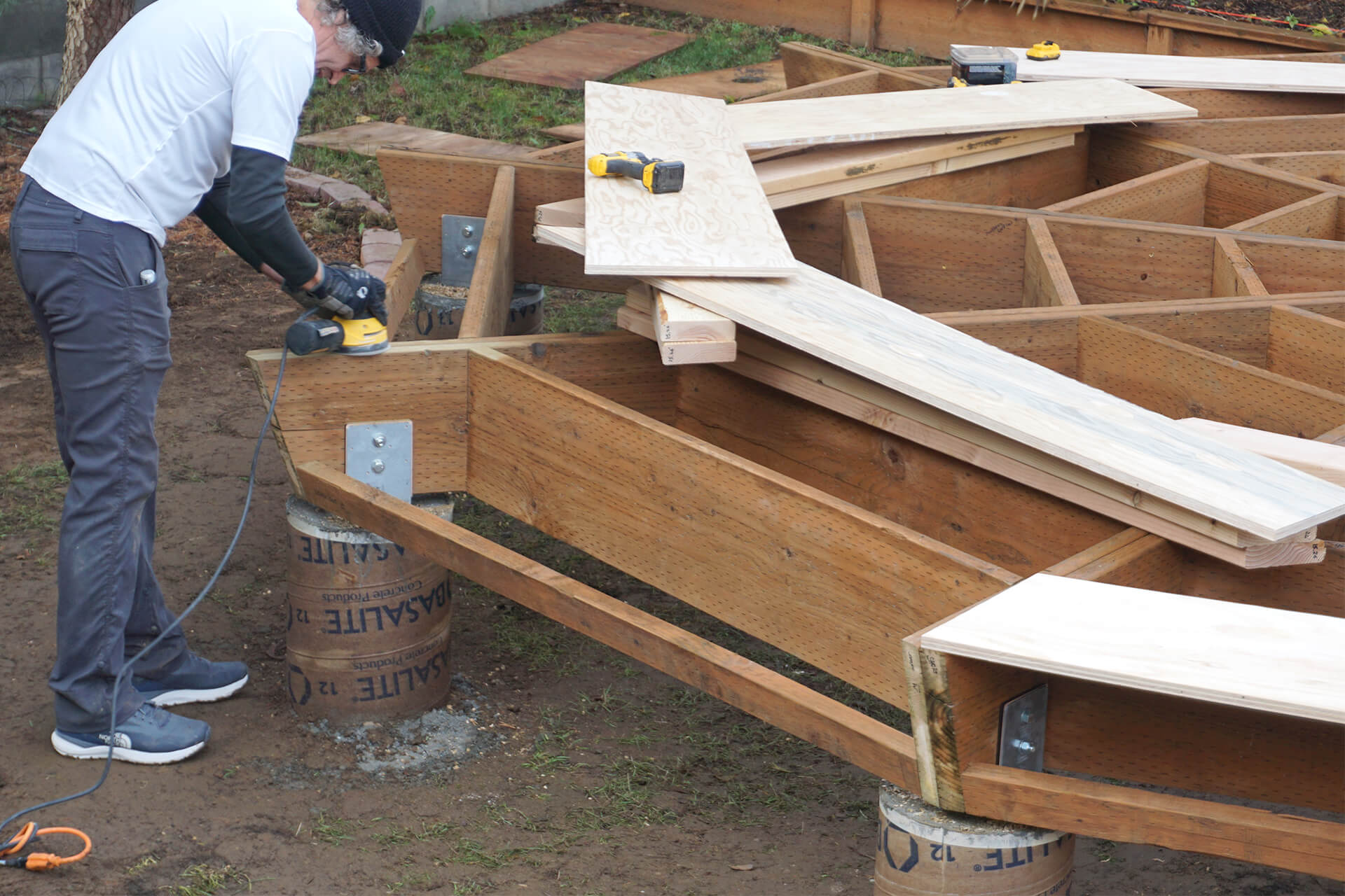
Attach the Subfloor-C panels. Sand or power-plane the mounting surface to ensure a nice and flat subfloor. Pre-drill and screw accordingly.
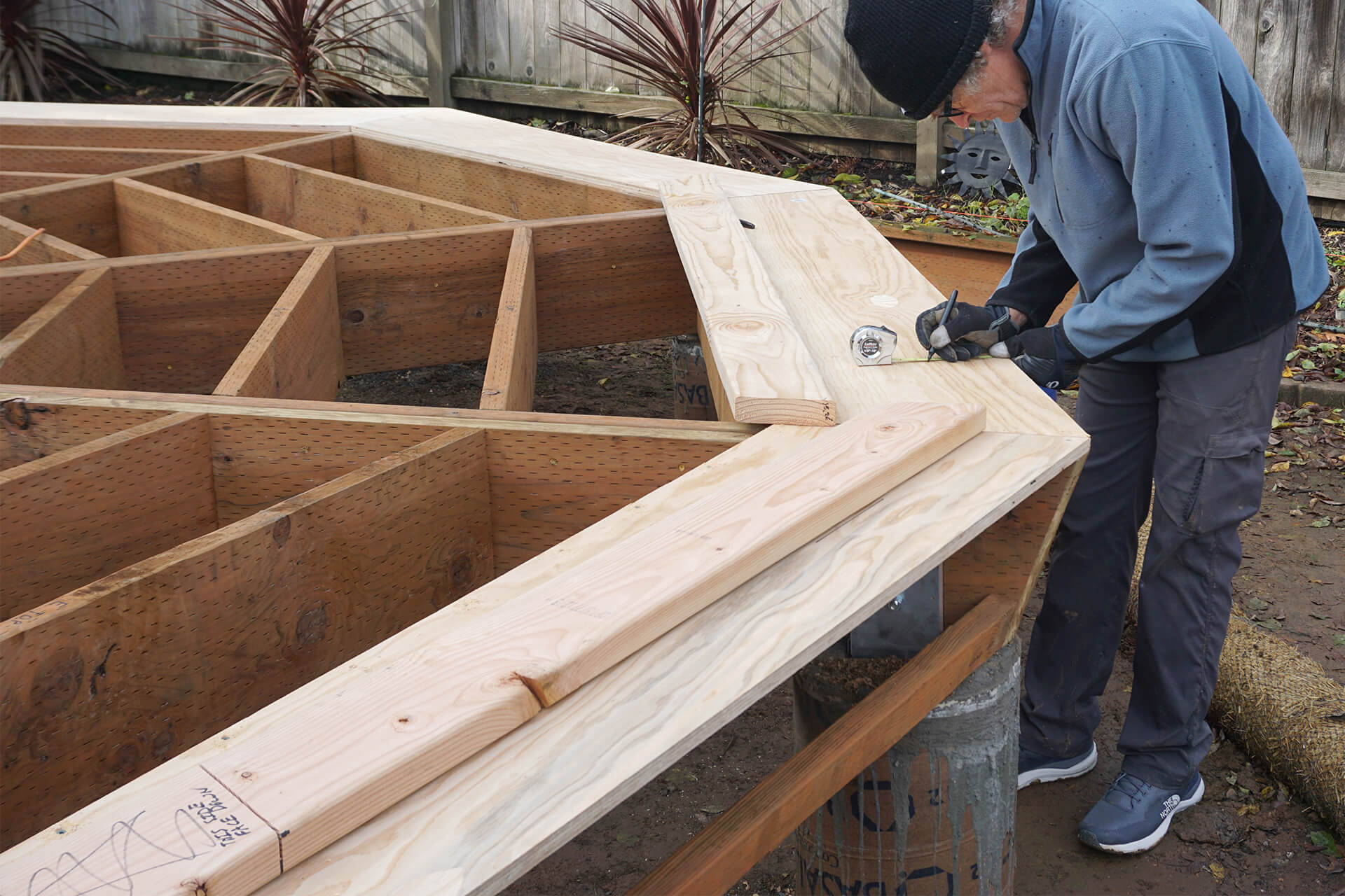
Mark the Sill-Plate-In locations onto the Subfloor-C panels. Then, lay out the Sill-Plate-Ins. They should all align perfectly, and hit the target location when properly laid out.
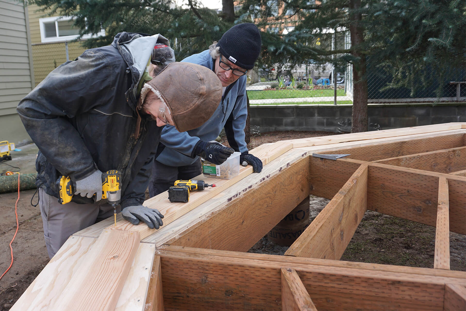
Attach the Sill-Plate-Ins. Pre-drill and screw the ends so that they are secured into the Floor-Beams. Screw from below to attach the Sill-Plate-Ins to the Subfloor-C panels.
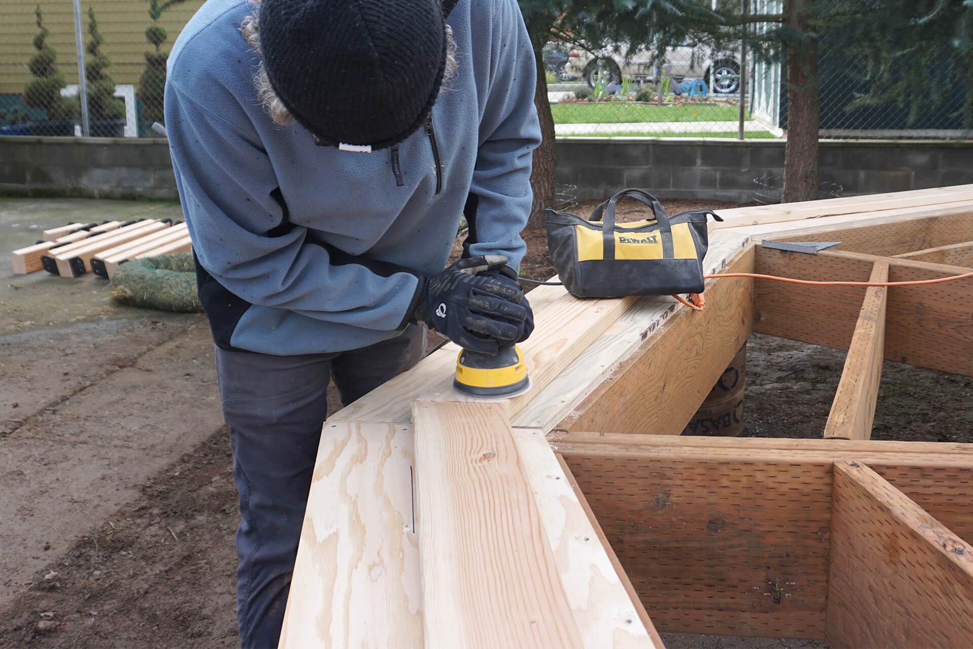
Sand or power-plane the newly attached Sill-Plate-In corners to ensure a nice and flat surface.
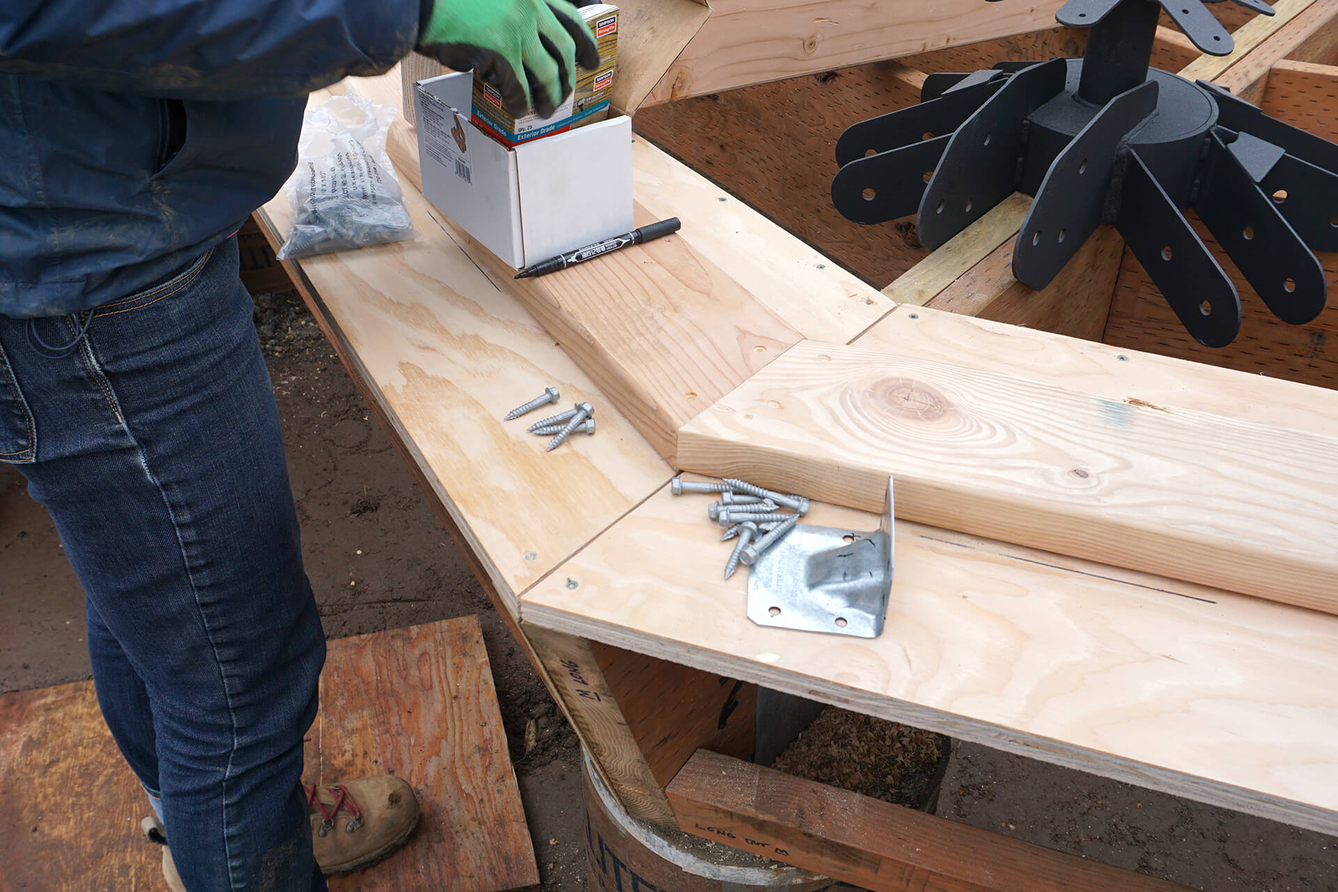
Secure the Sill-Plate-Ins directly to the Floor-Beams with gussets.
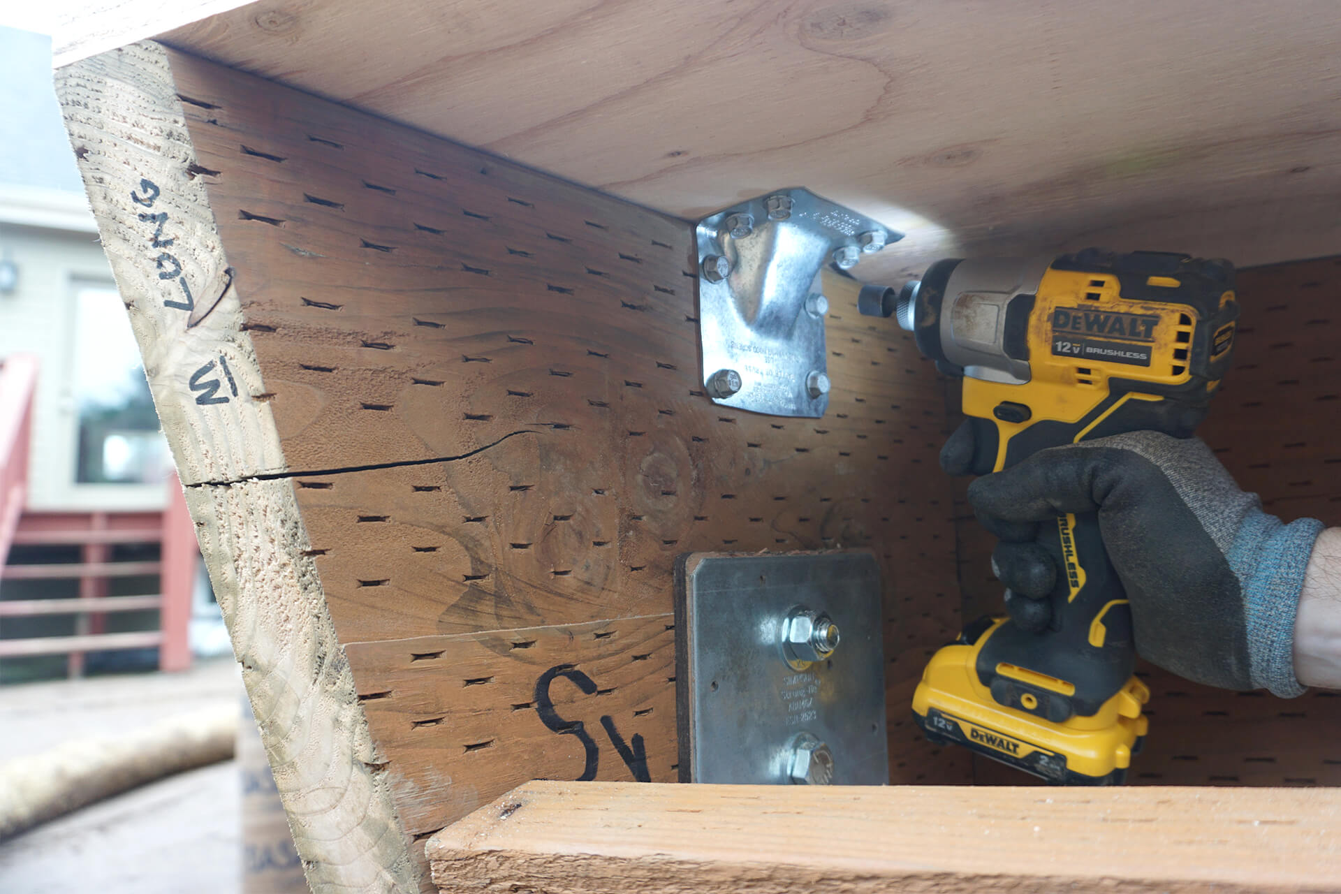
Attach the gussets to both sides of the Floor-Beams. They strengthen the load path and prevent upward and lateral forces from shifting the Sill-Plates.
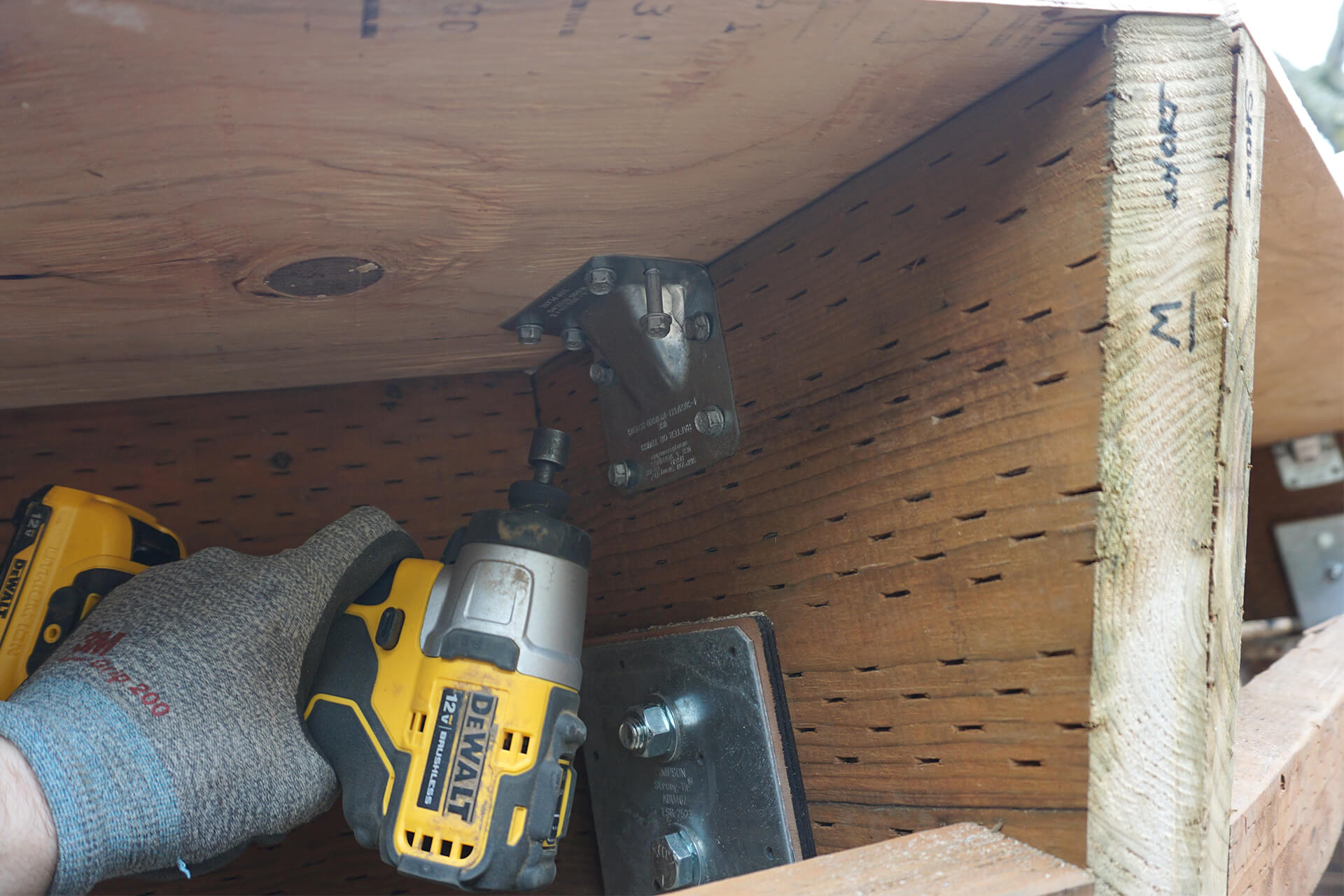
After sill plates and gussets are installed, call for an inspection. Work can continue so long as everything is visible and accessible for inspection.
Inspection: Underfloor / Post and Beam
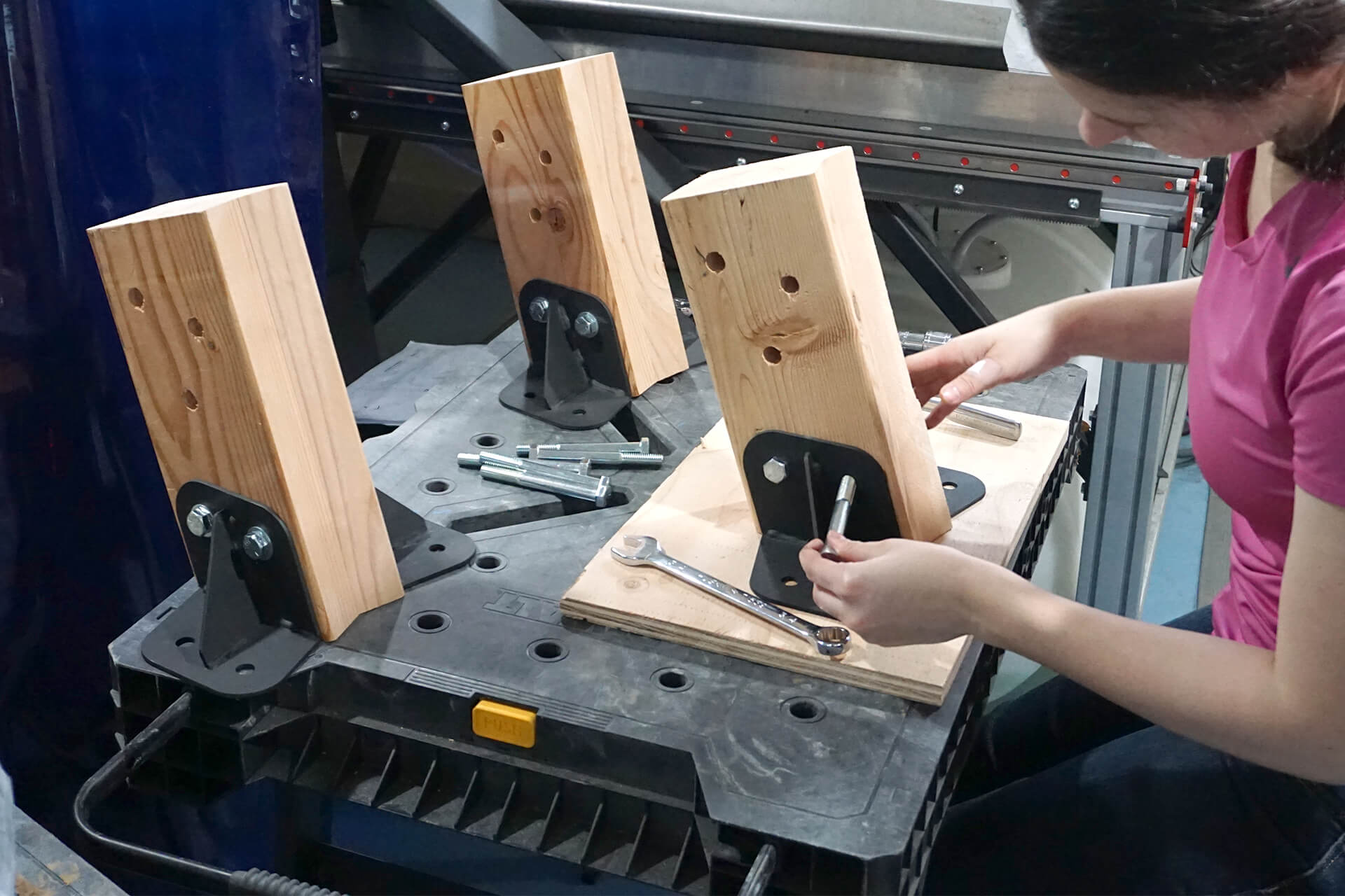
Create sub-assemblies of the Strut-Base-Talls (not shown) and Strut-Base-Shorts (shown) by attaching the steel Base-Brackets. Do so on a very flat surface.
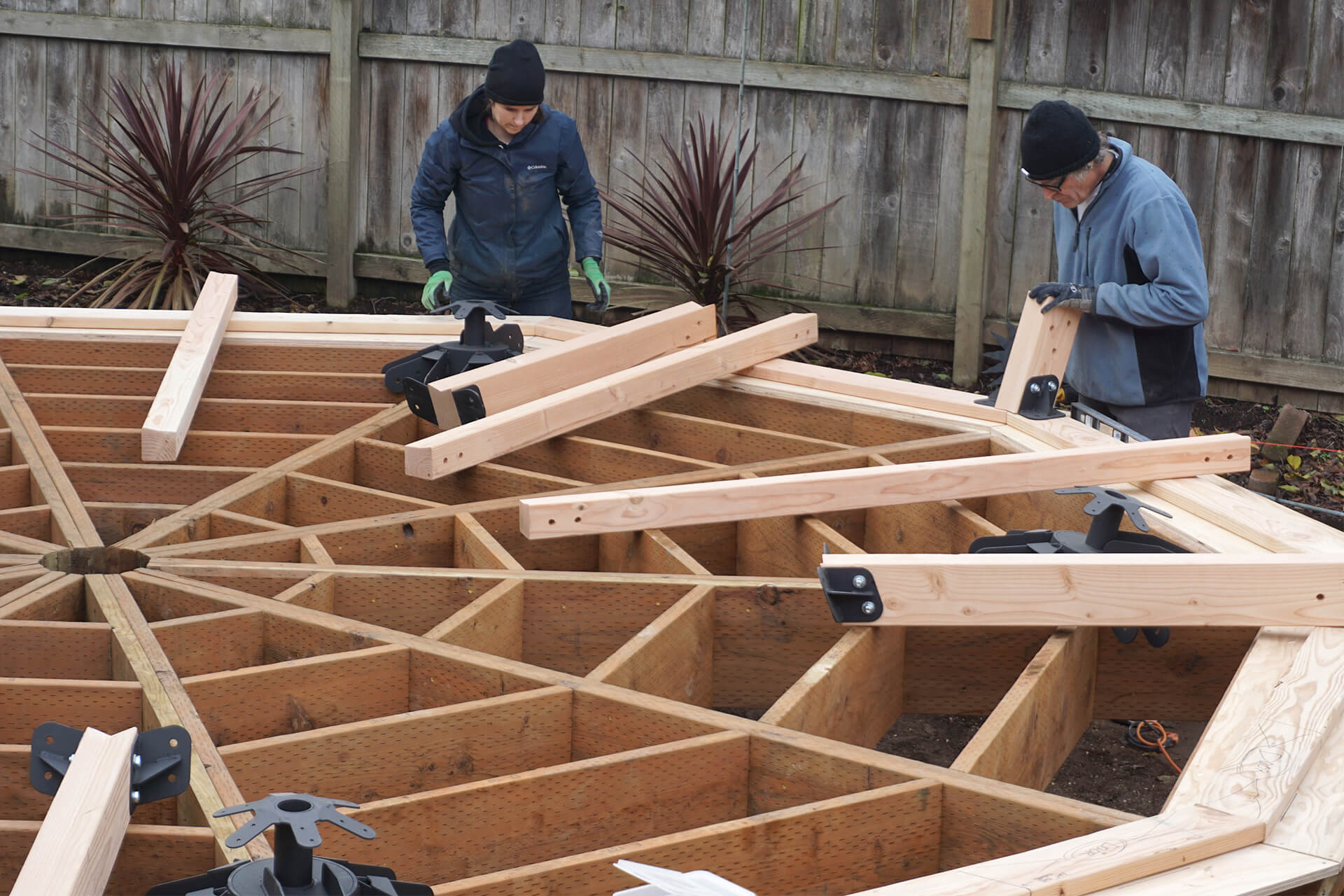
Lay out the sub-assemblies in their respective positions. Gather and lay out the steel Base-Hubs and Strut-Bases as well.
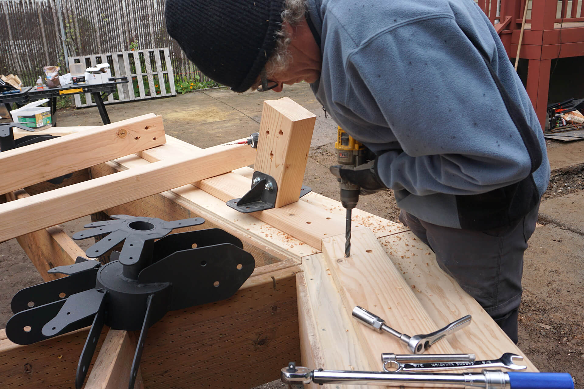
Mark the bolt hole locations of the steel Base-Connectors and drill through the Sill-Plate-Ins and Subfloor-Cs.
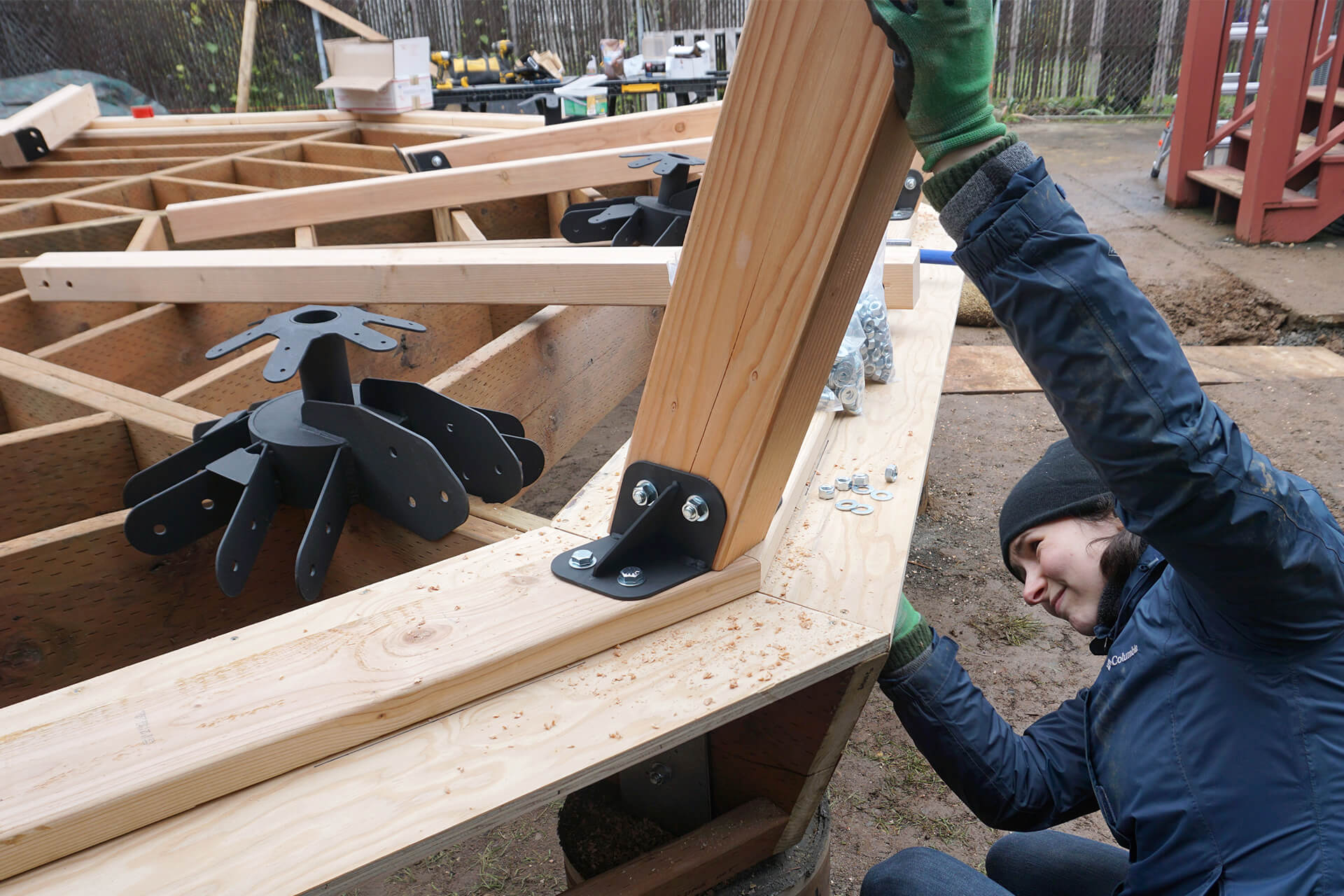
Secure the steel Base-Brackets with bolts, washers, and nuts. They can temporarily be left snug (not fully tightened) to allow for minor movement during assembly.
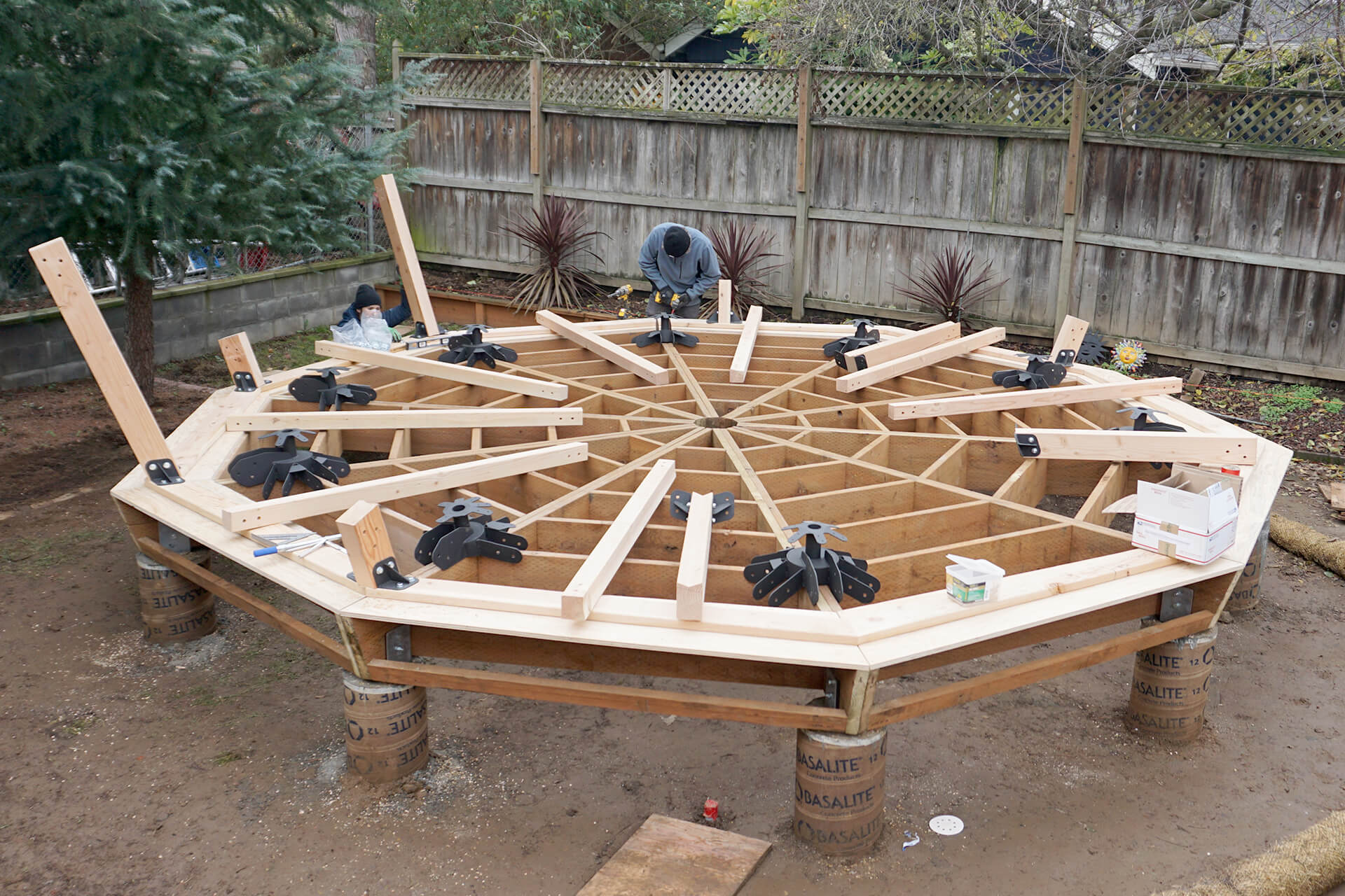
Install all of the Strut-Base-Tall and Strut-Base-Short sub-assemblies.
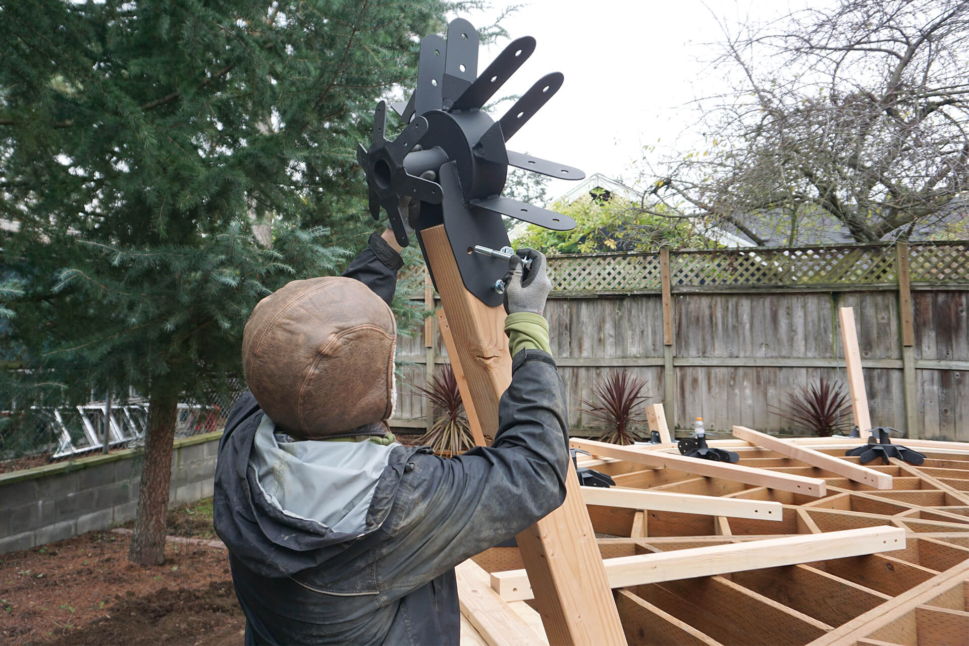
Secure the steel Base-Hubs to their respective Strut-Bases. They can temporarily be left snug (not fully tightened) to allow for minor movement during assembly.
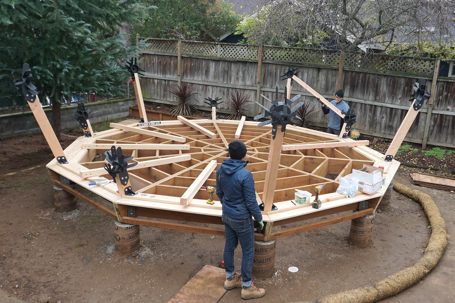
Attach the Strut-Bases between the steel Base-Hubs.
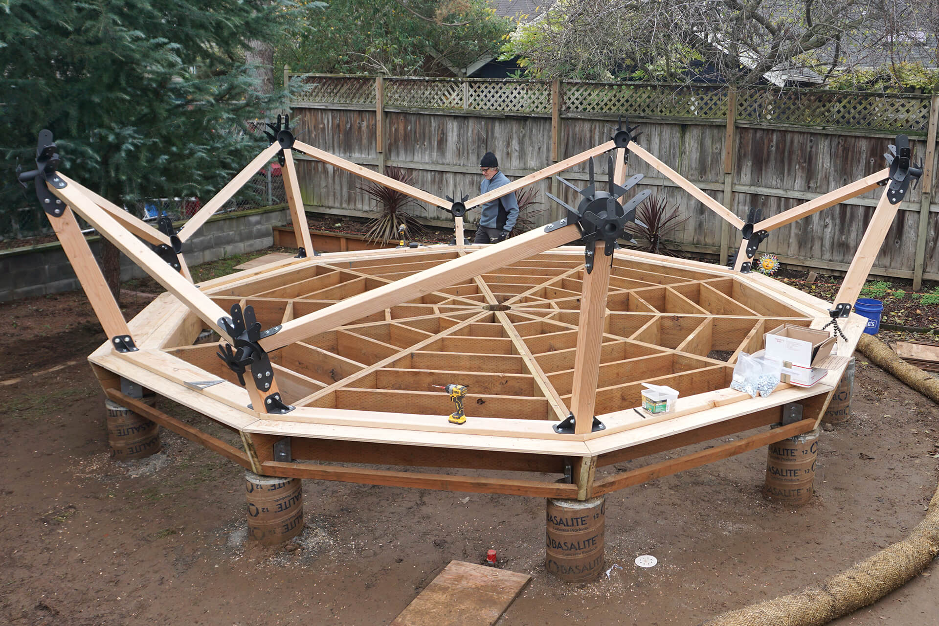
Install all of the Strut-Bases.
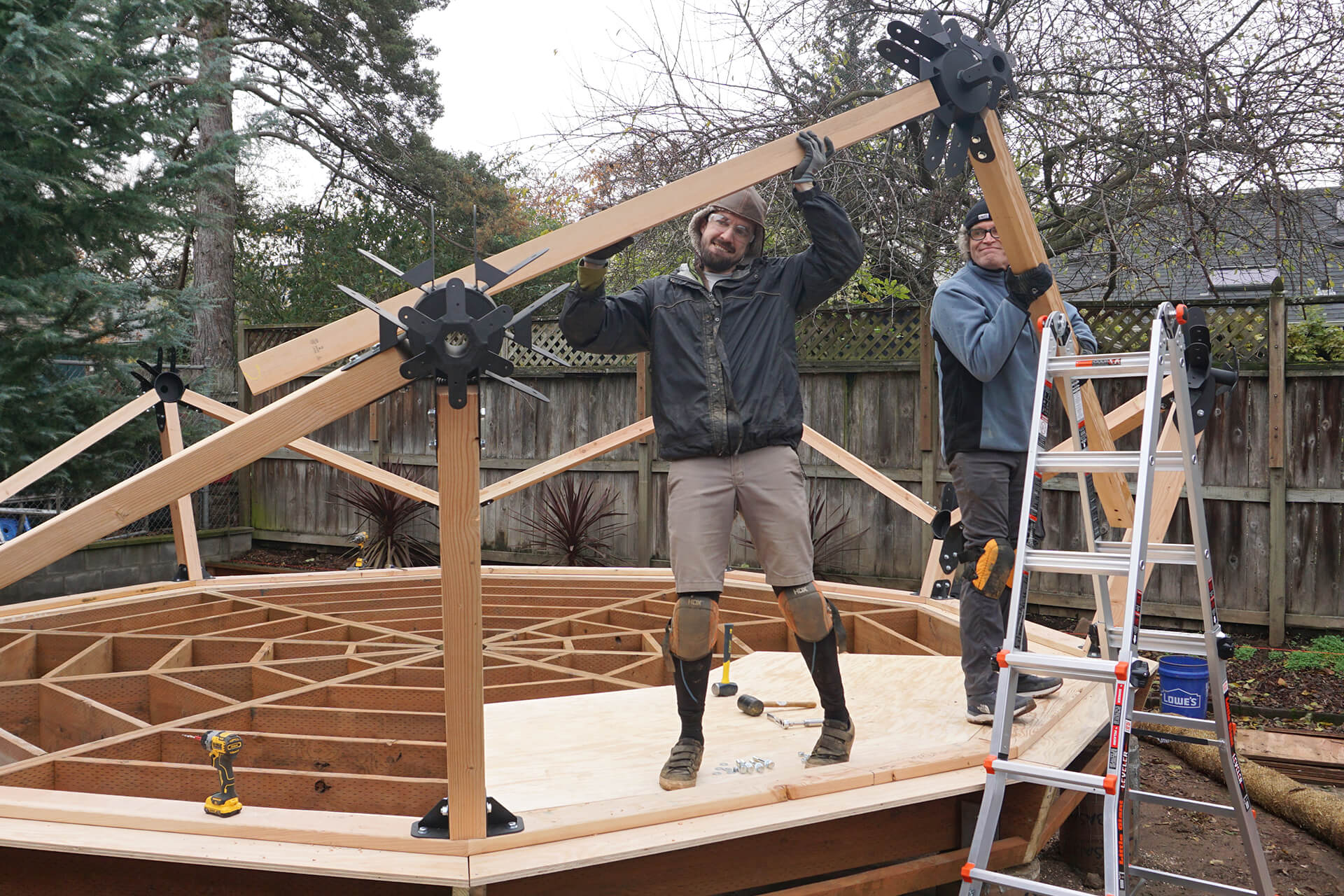
Create the over-door sub-assembly, consisting of a steel 6F-Hub and two Strut-Longs, and then secure it to the steel Base-Hubs that span the door opening.
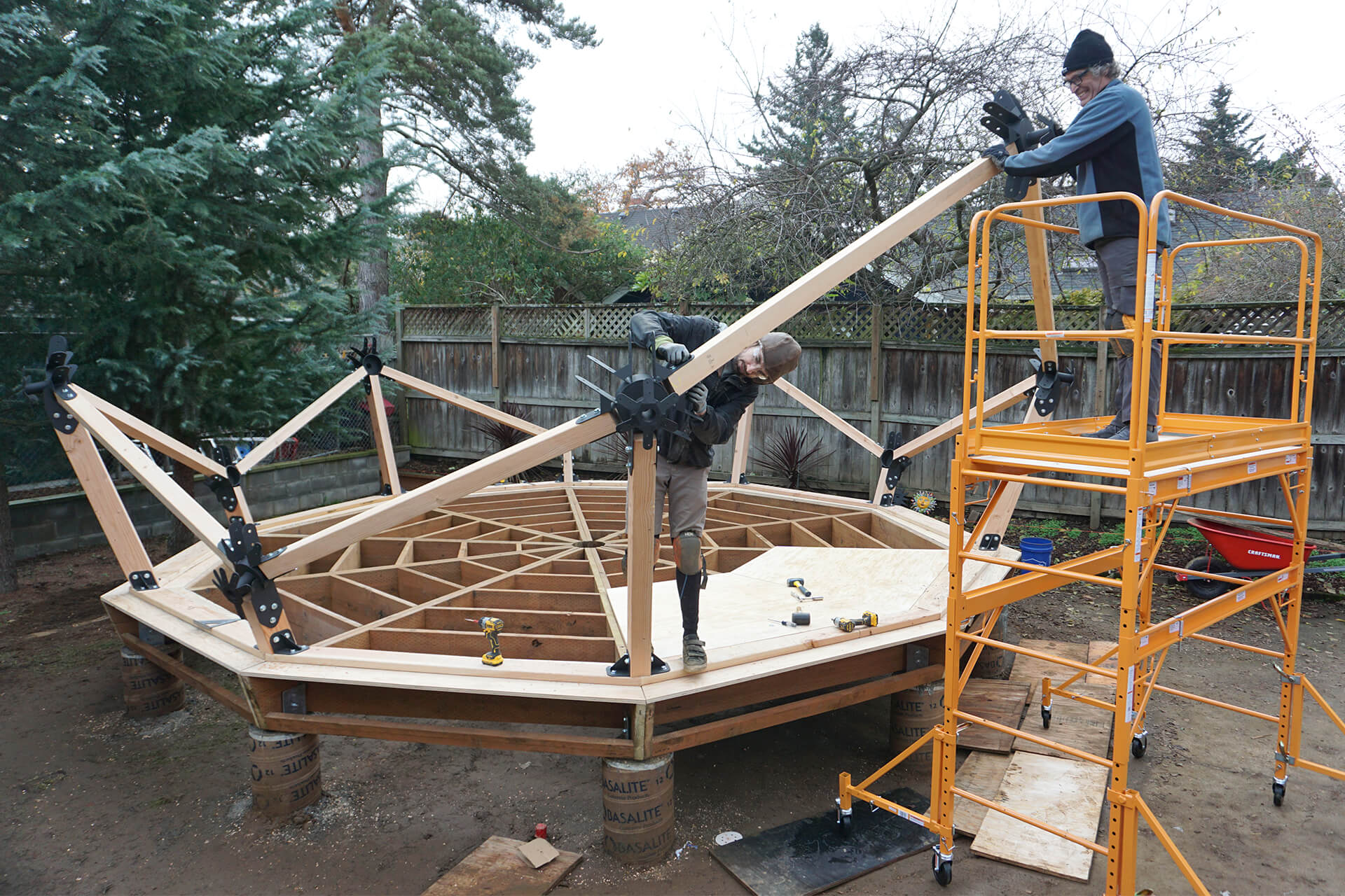
Set up the scaffolding outside of the dome to aid in assembly. Use a ratchet strap (seen in other photos) to apply some tension between these two steel Hubs. This will make assembly easier.
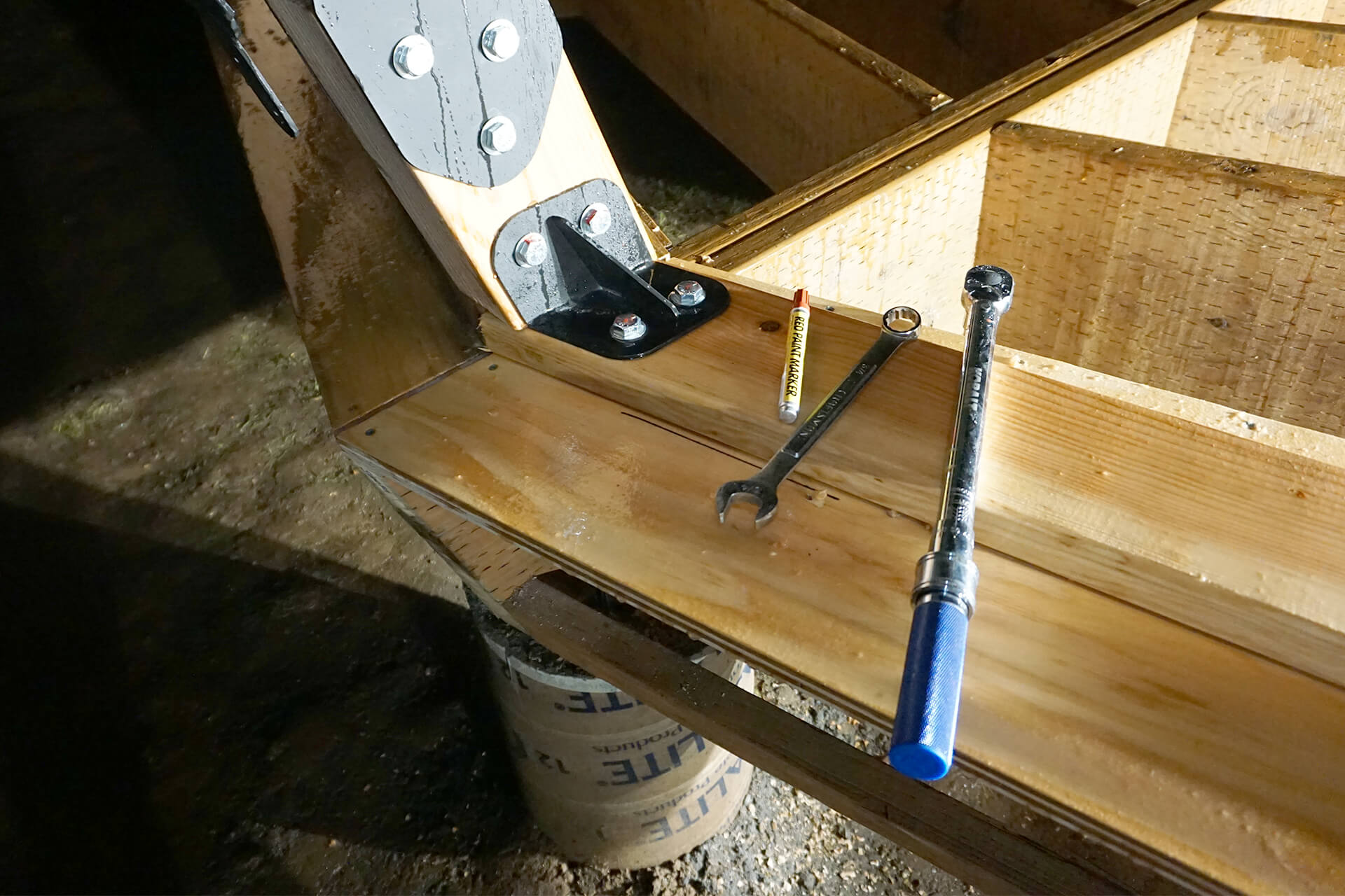
Torque all connections to 65 lb-ft, and mark the bolts and nuts to keep track.
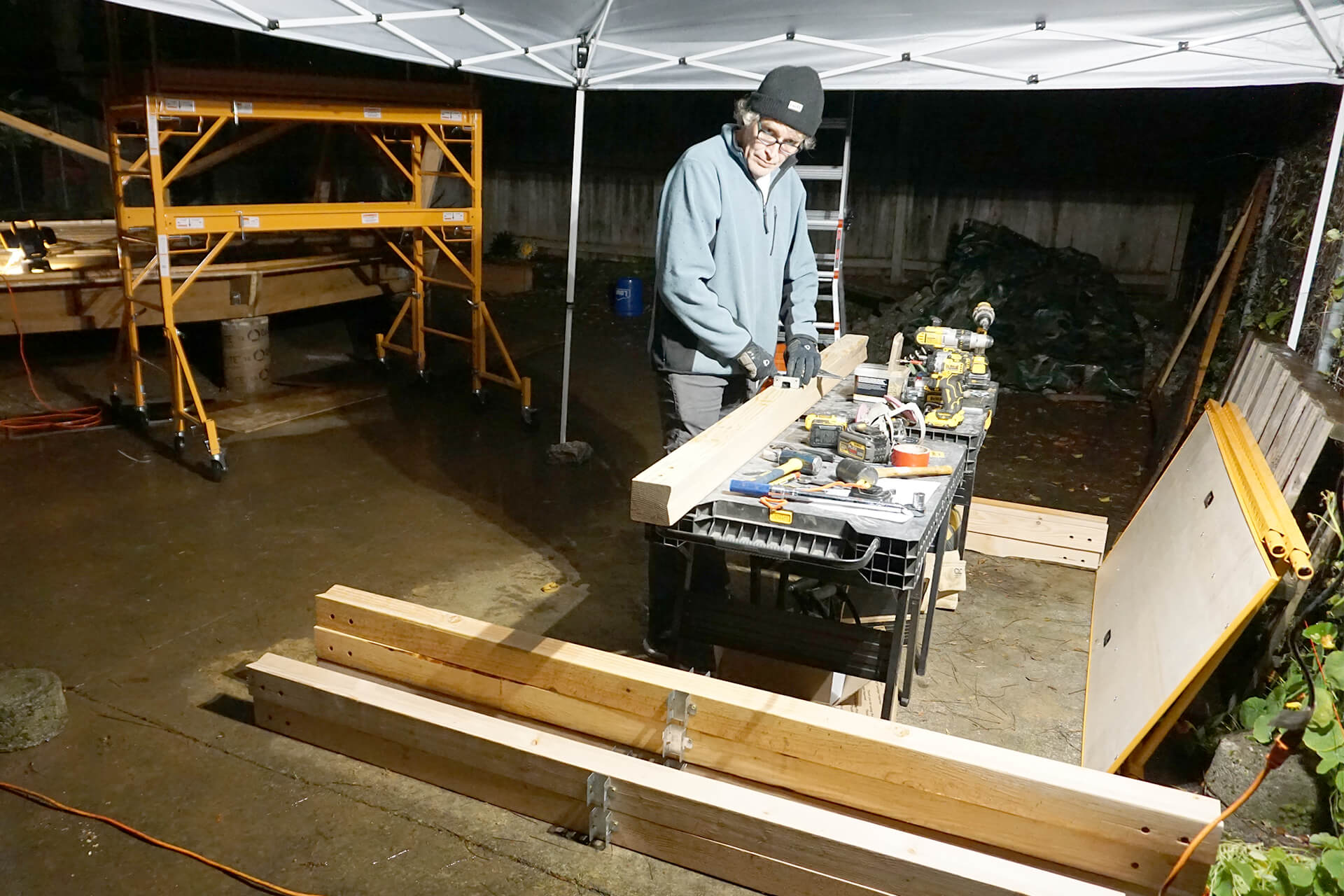
Attach the stud holders (Simpson RTR) to both sides, centered on the Stud-Longs. It is easier to attach them on a bench now rather than during assembly.
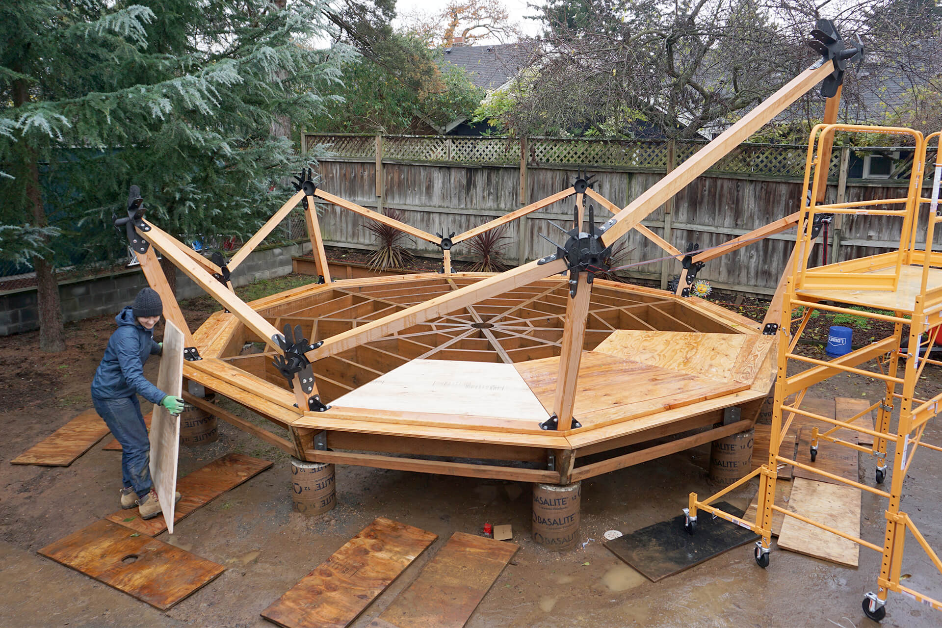
Lay down the Subfloor-B panels without attaching them, as they will need to be removed later. Lay down the Subfloor-A panels as well (not shown until later due to rain).
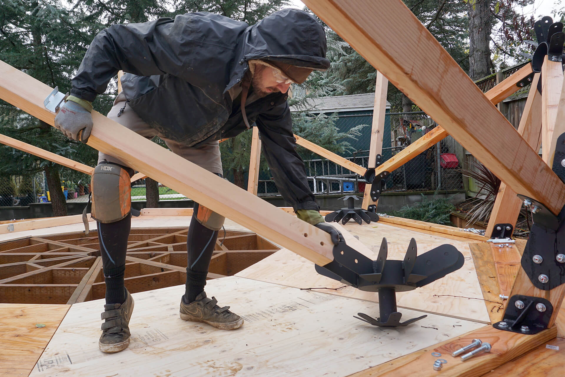
Create sub-assemblies of the Strut-Longs and the steel 6F-Hubs to speed up assembly. Only do this if working with a helper; otherwise attach one component at a time.
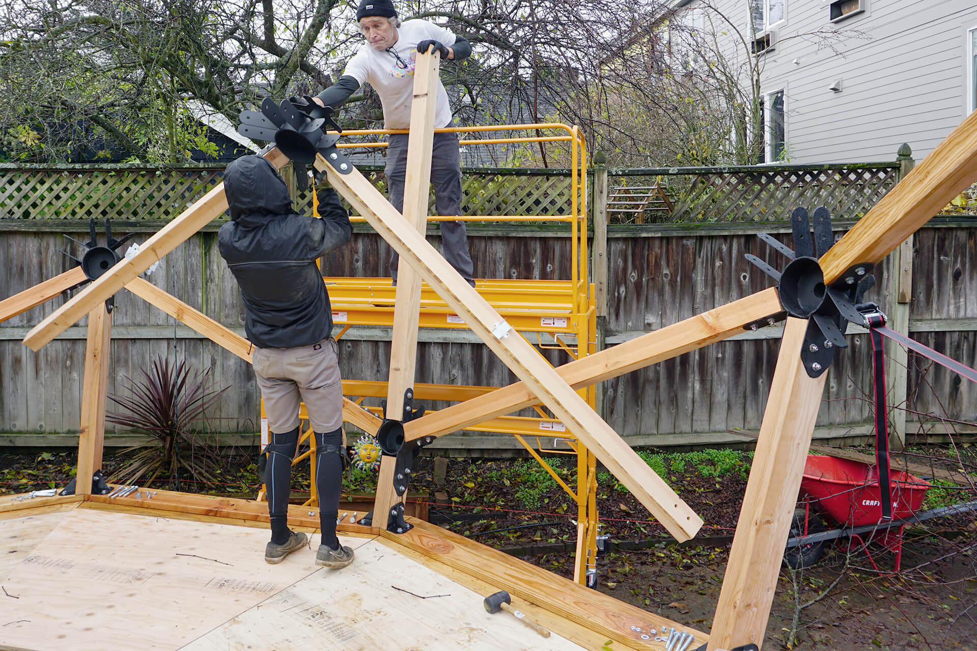
Attach a Strut-Short vertically to the 4F-Base-Hub, then lift and attach the newly created sub-assembly atop it.
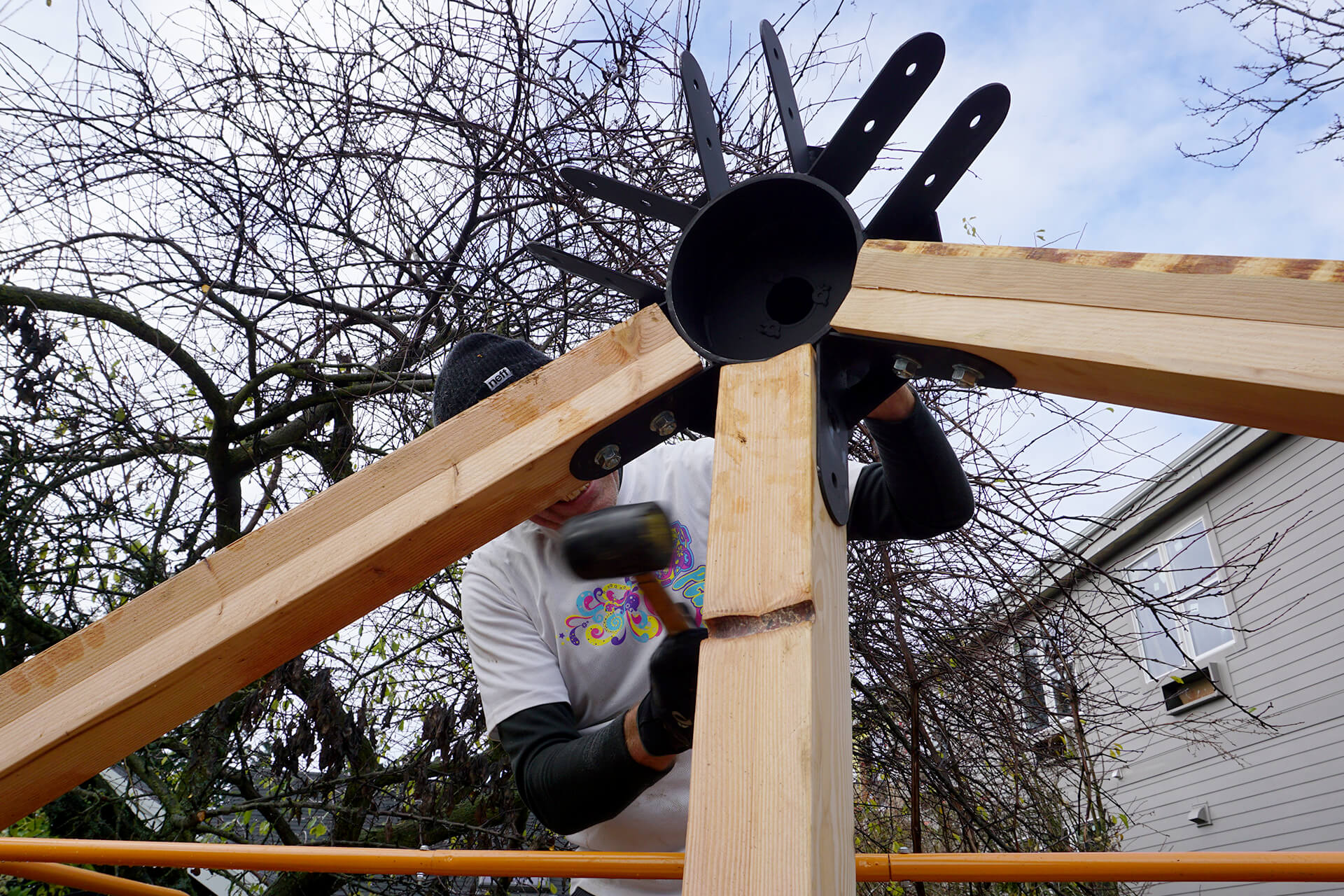
Use a rubber mallet to tap stubborn bolts through holes or to adjust components slightly.
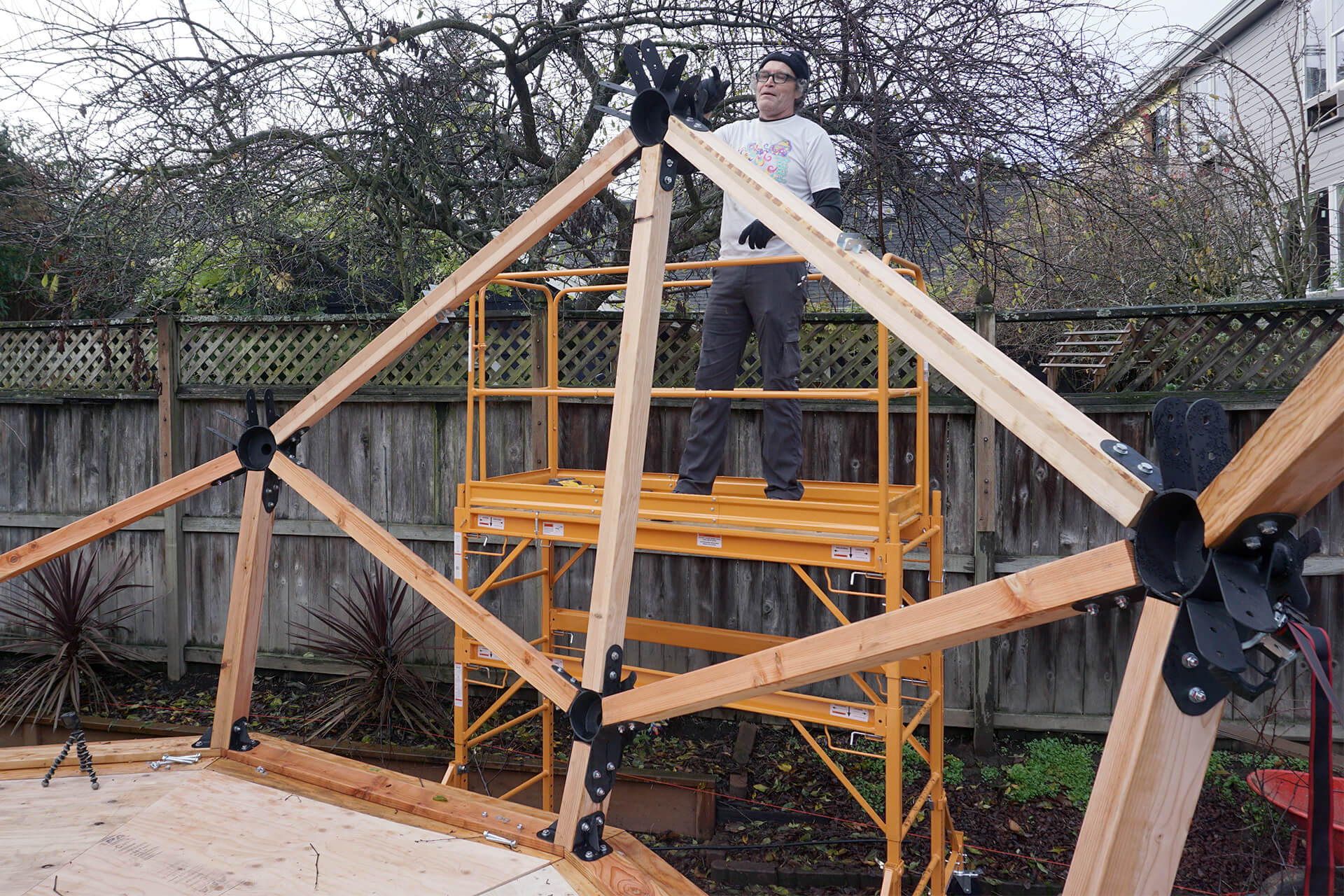
A completed section.
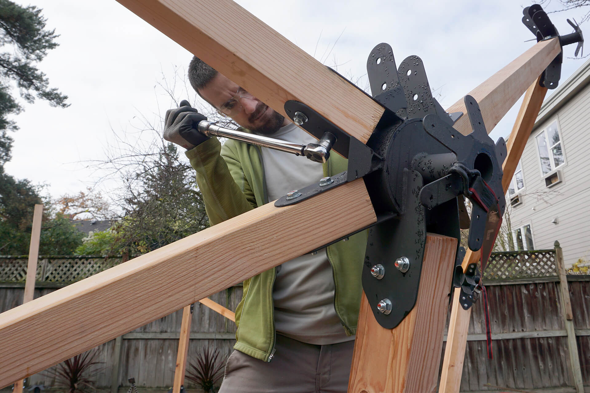
Torque and mark the fasteners for each completed section.
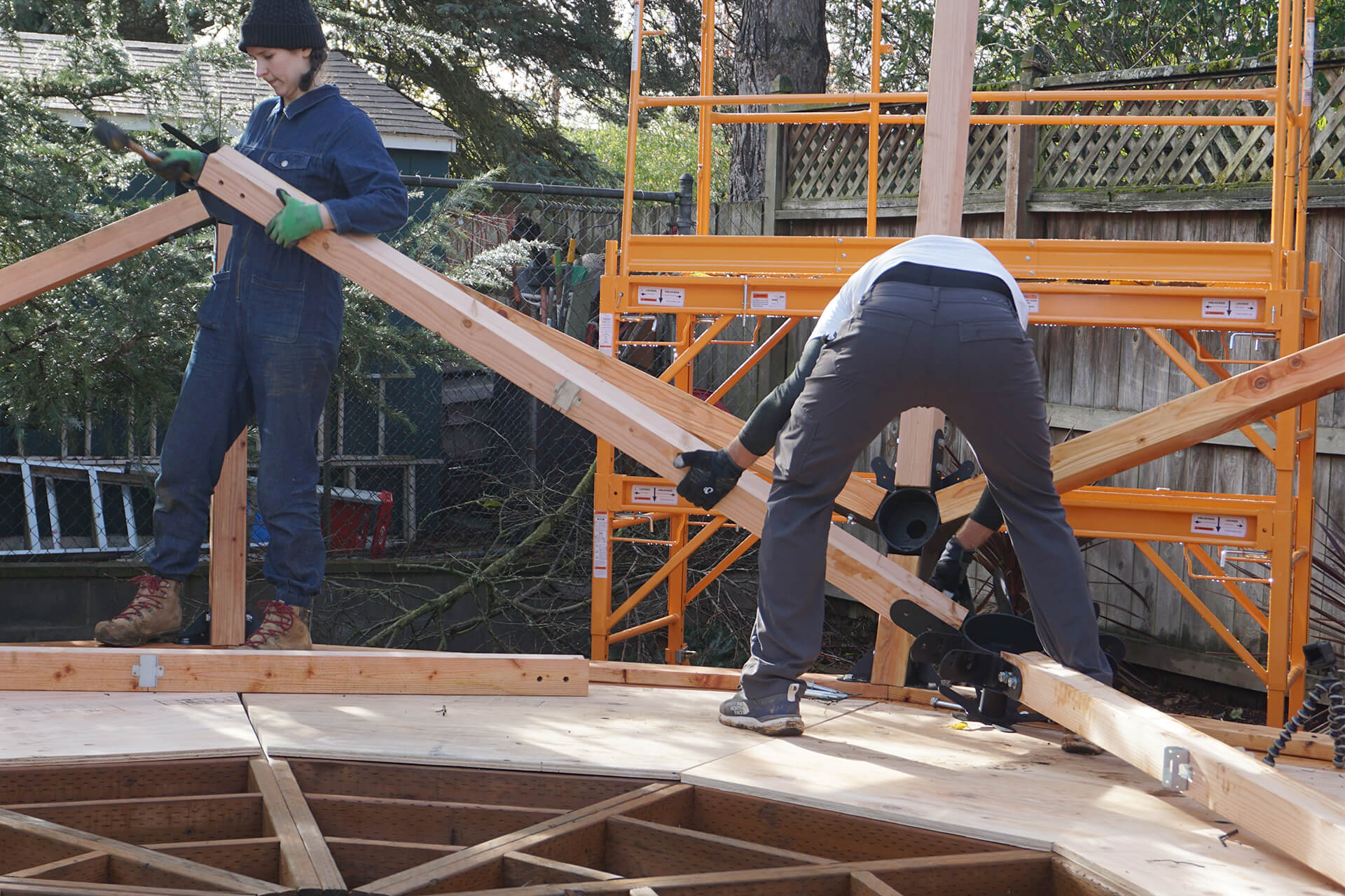
Repeat steps of attaching sub-assemblies atop vertical struts until another row of sections is completed.
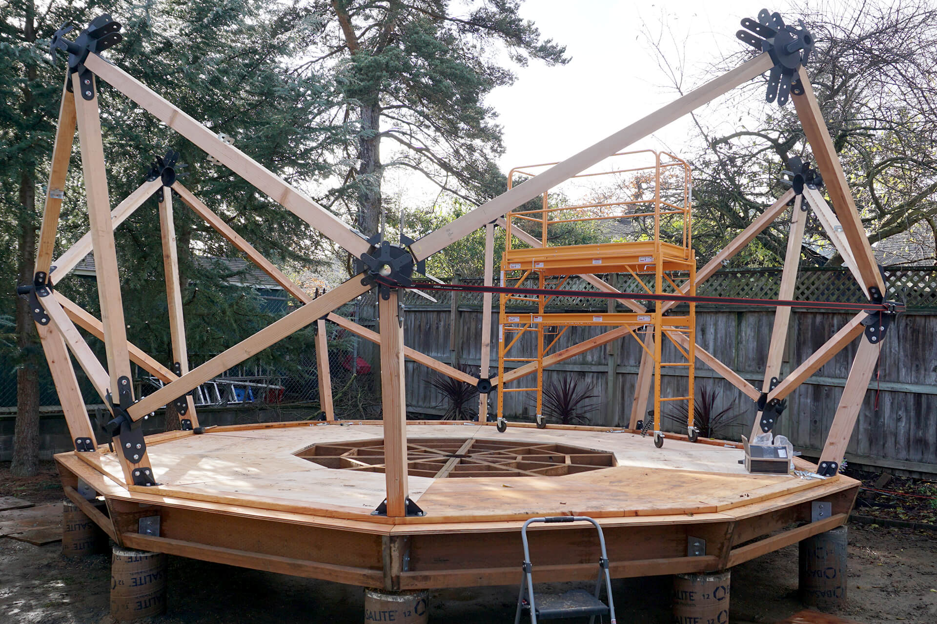
Use a ratchet strap to apply tension between the steel Hubs on either side of the door opening, then set up the scaffolding inside the dome.
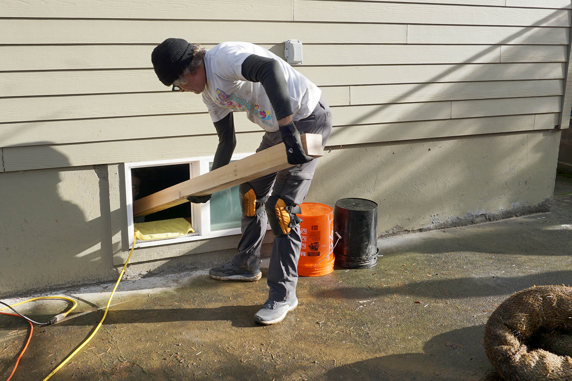
Gather the Struts for the next row. Passing lumber out of a window is too fun not to photograph.
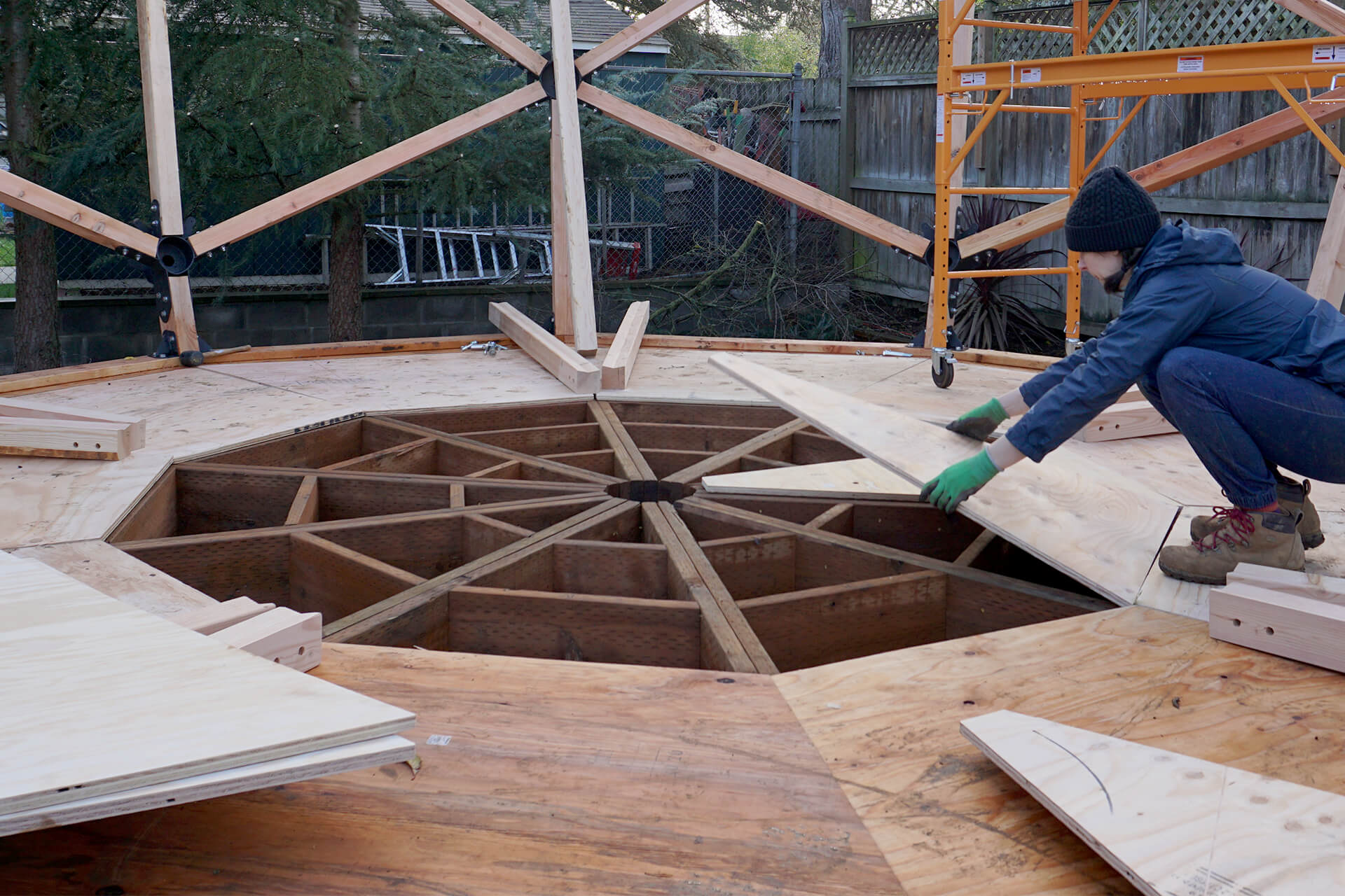
Lay down the Subfloor-A panels if they are not already in place. Do not attach them, as they will need to be removed later.
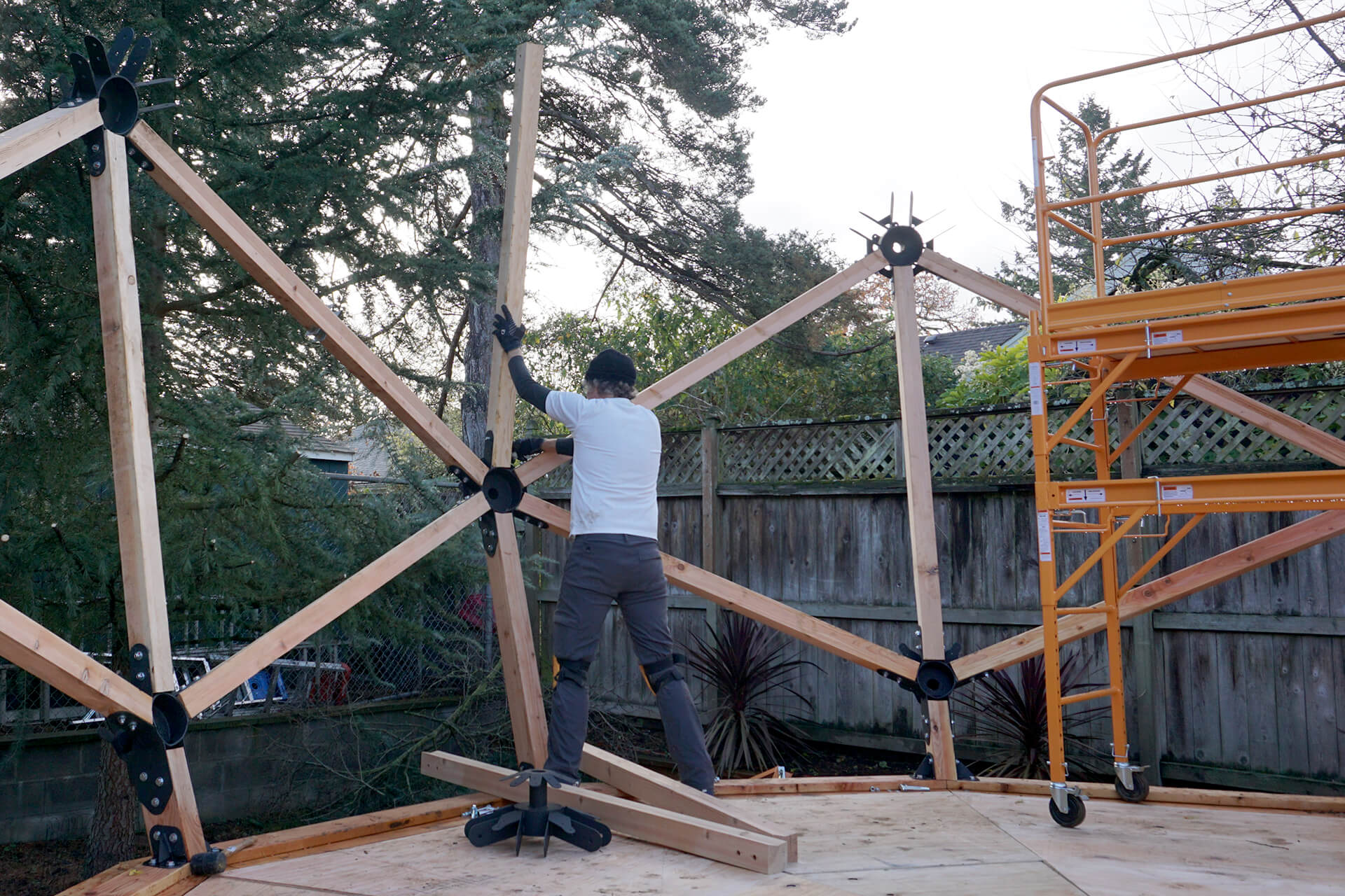
Attach a Strut-Short vertically to the 6F-Base-Hub.
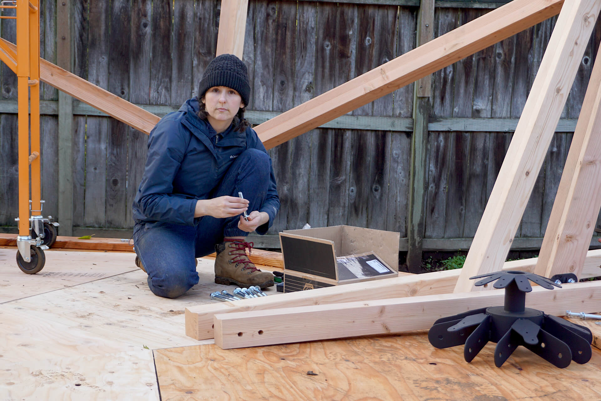
Build sub-assemblies comprised of 5F-Hubs and two Strut-Shorts.
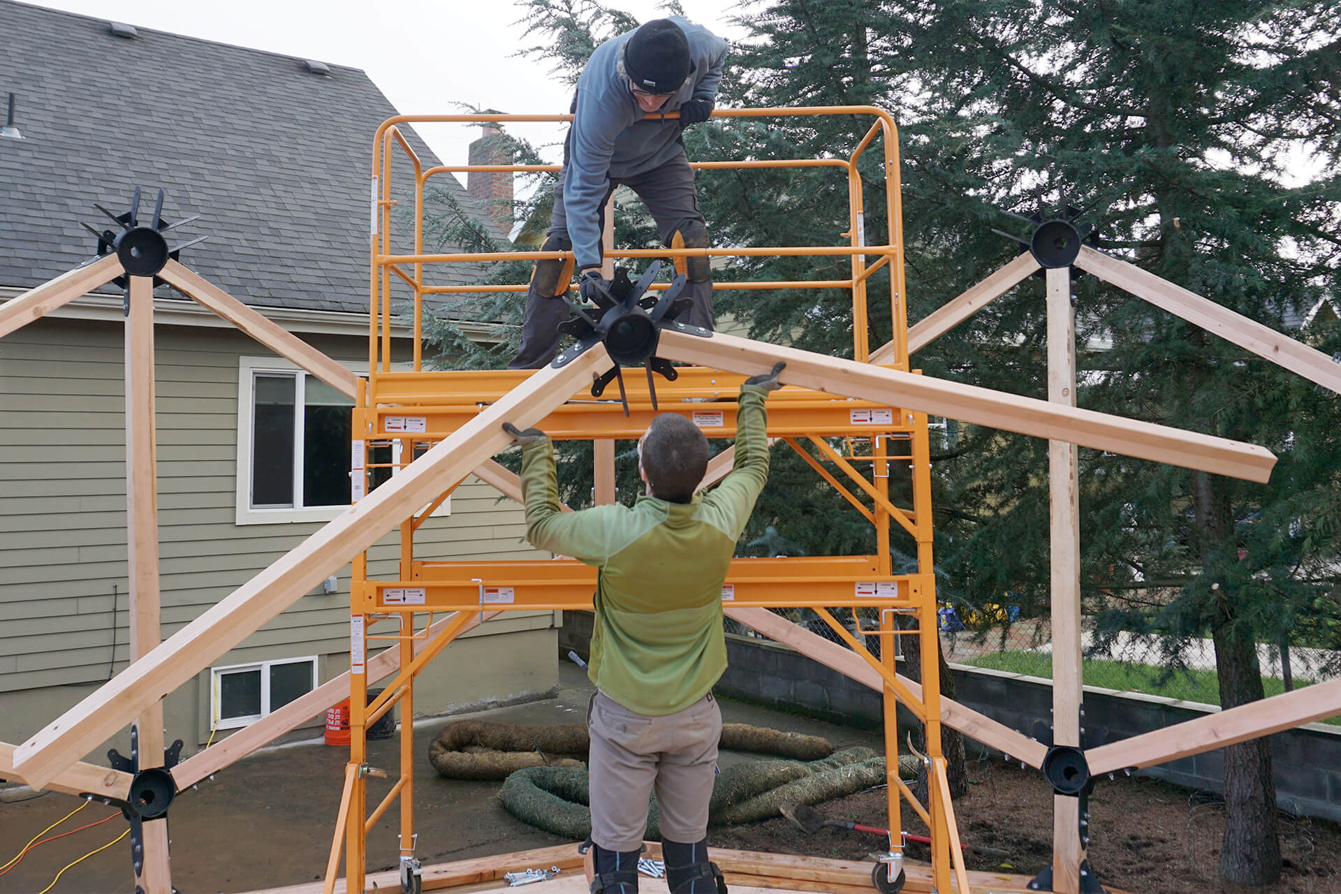
Lift and attach the newly created sub-assemblies atop the vertical Strut-Shorts.
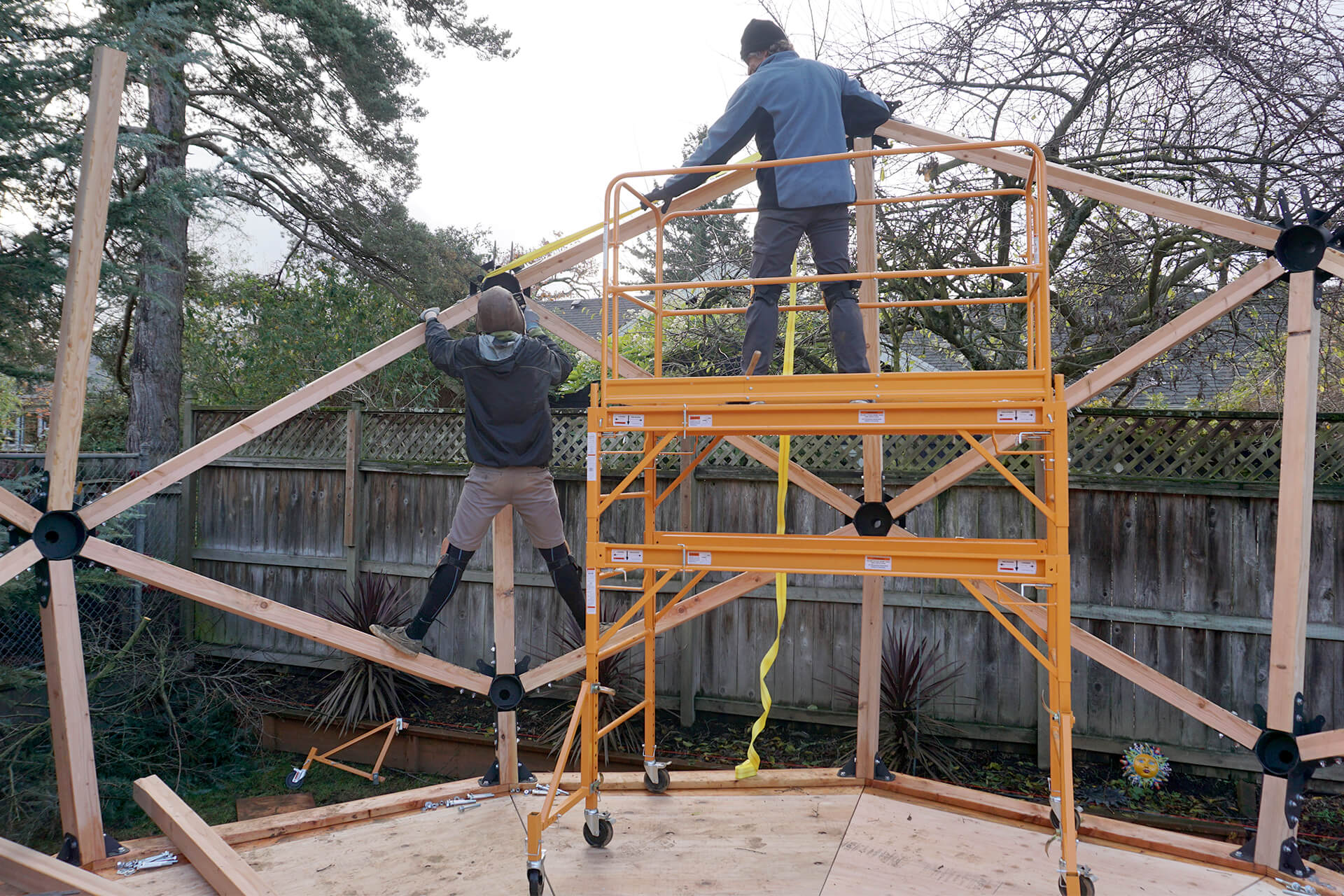
Use ratchet straps to aid in assembly, as they allow for minor flexing of the unfinished structure. This is one of many techniques that can help achieve proper fit.
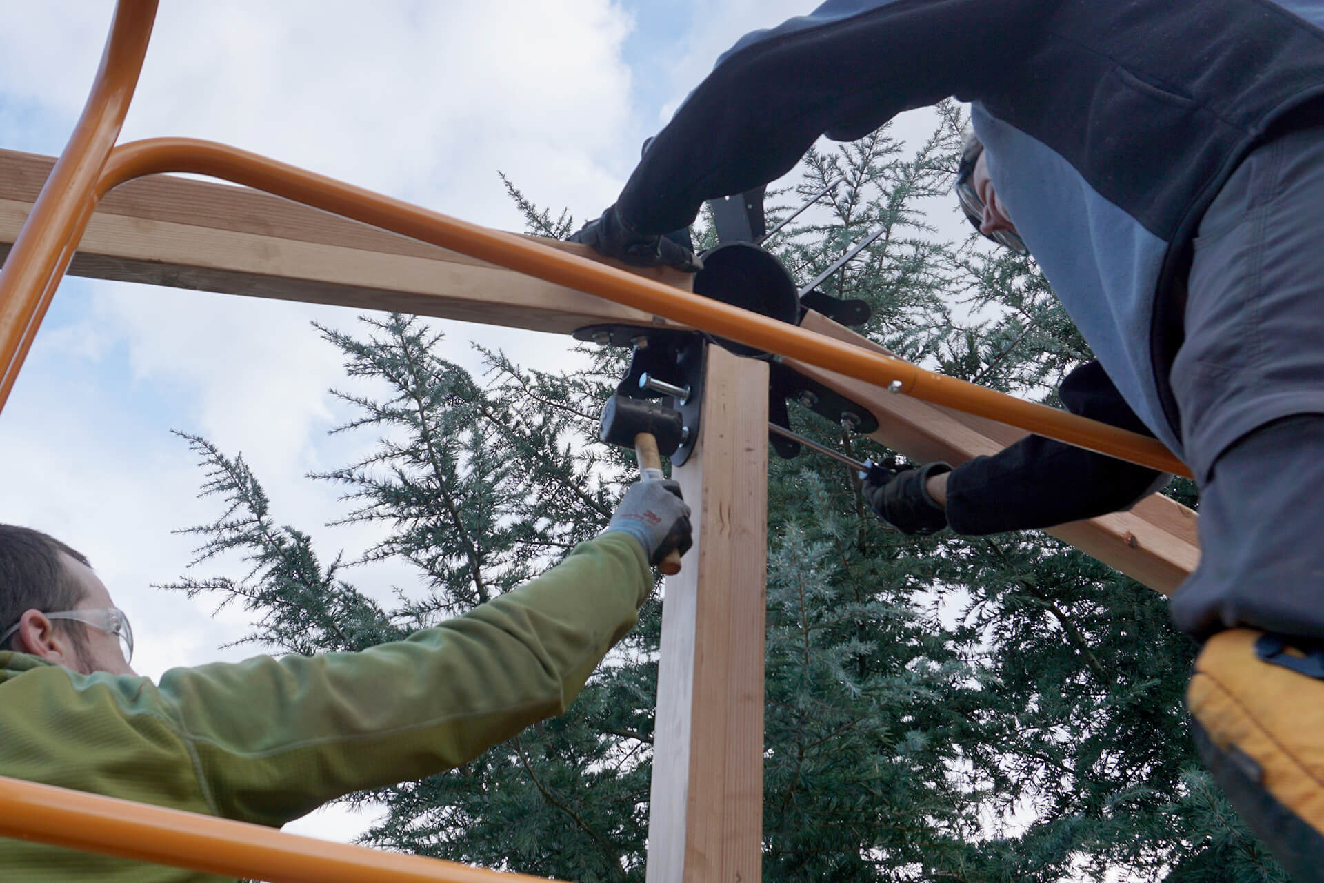
Use a large screwdriver as an alignment pin. The leverage and shape help guide the bolt holes and bolt slots into alignment. A rubber mallet can also be used to tap a bolt through.
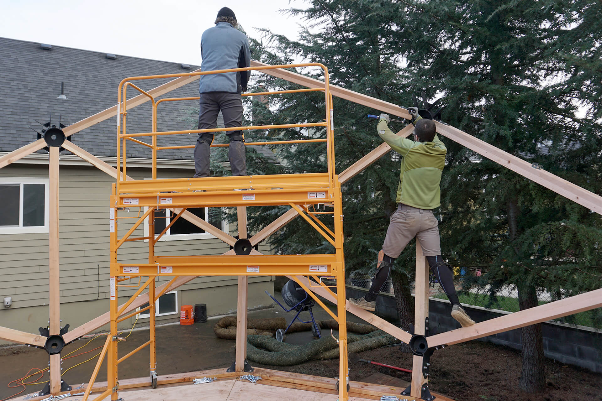
A completed section.
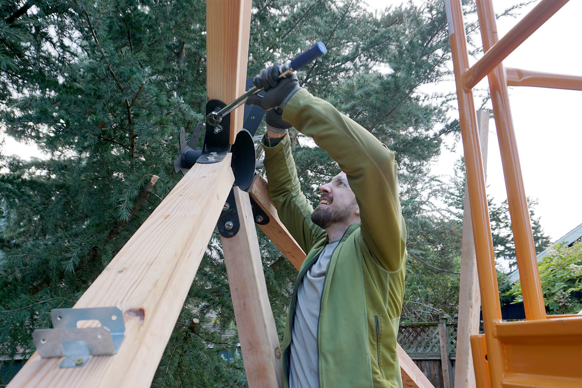
Torque and mark the fasteners for each completed section.
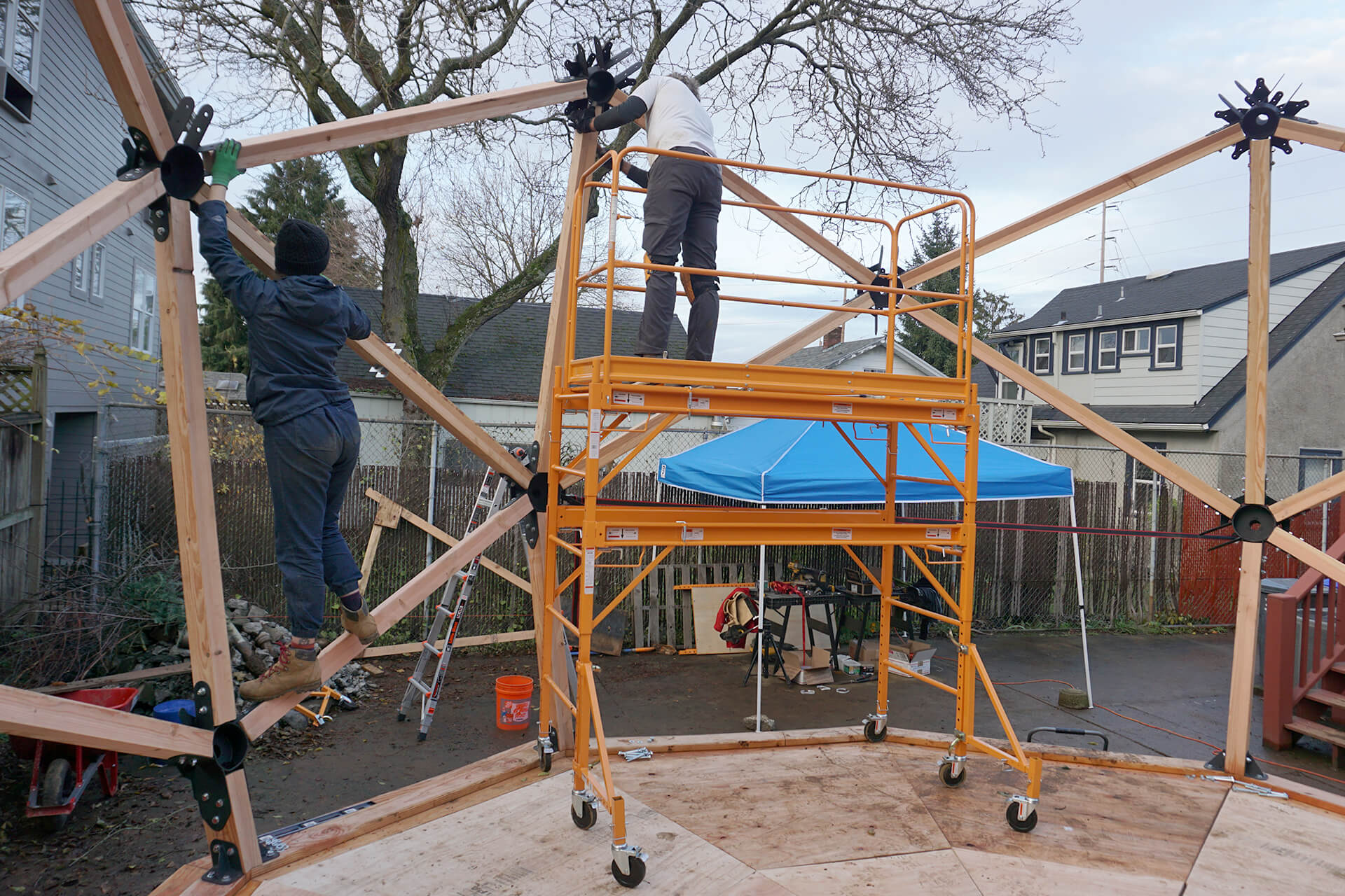
Repeat steps of attaching sub-assemblies atop vertical struts until another row of sections is completed.
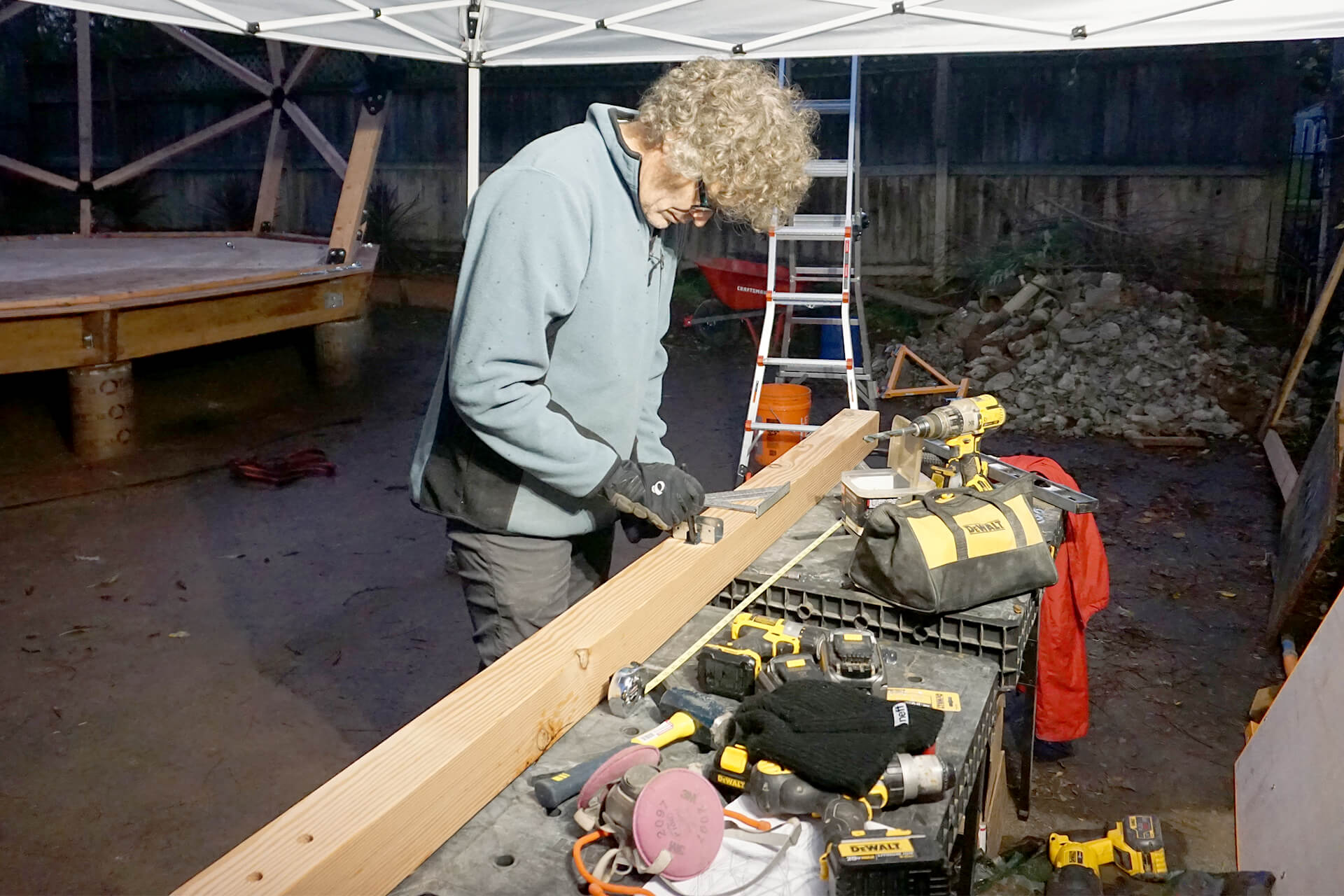
Attach more stud holders (Simpson RTR) to both sides, centered on the Stud-Longs.
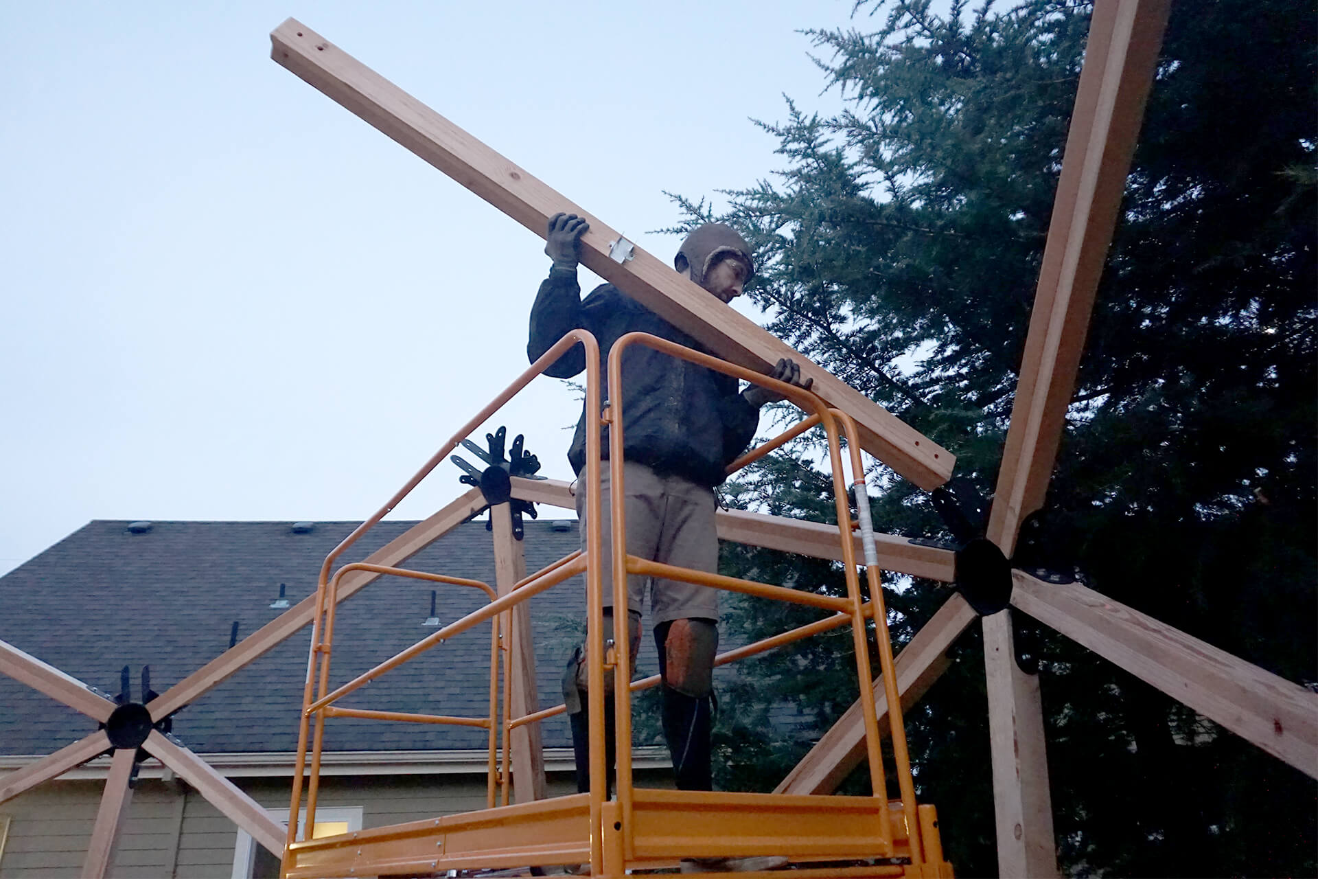
Attach those Stud-Longs vertically to the steel 6F-Hubs.
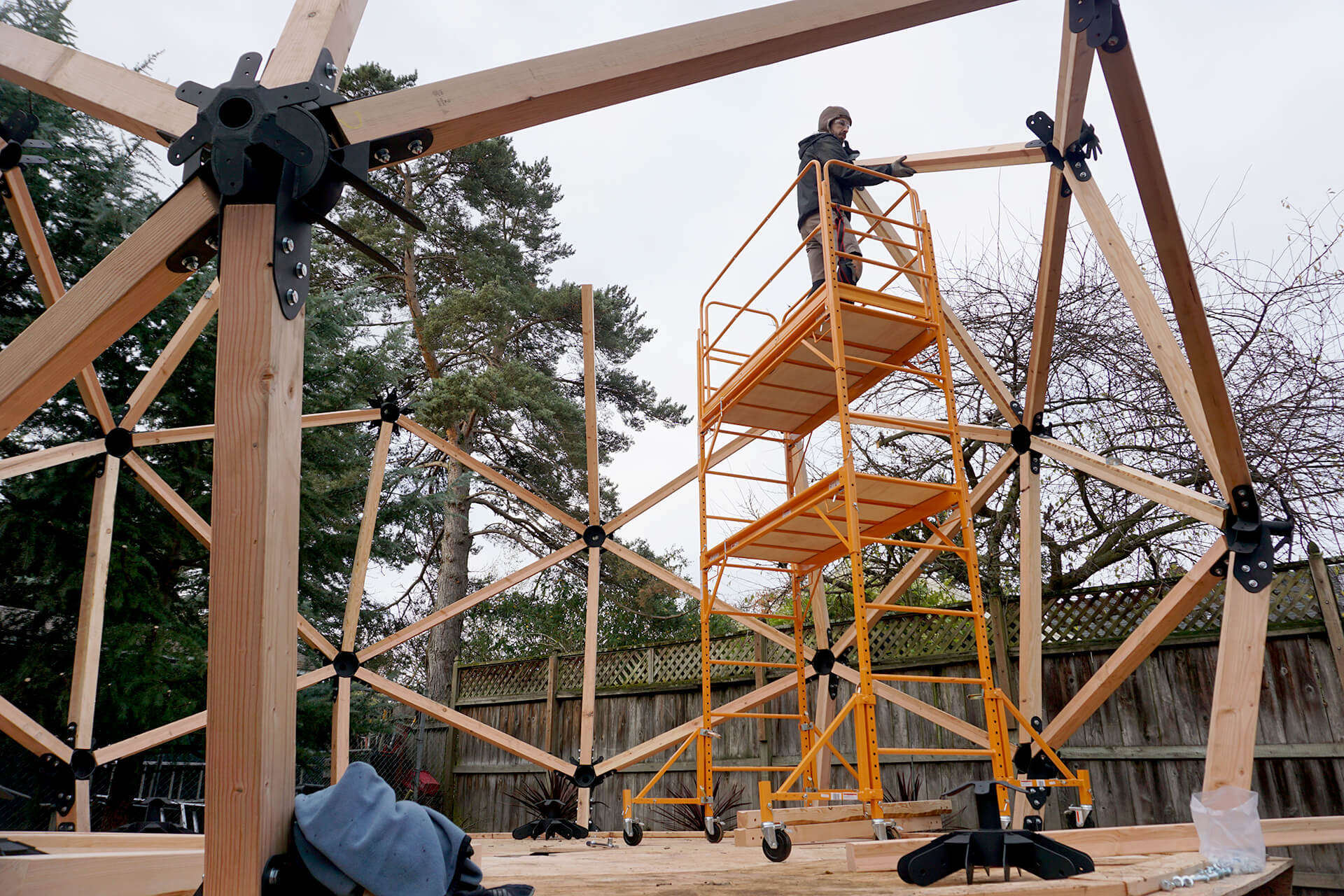
Raise the scaffolding and attach steel 6F-Hubs to the vertical Struts. Then, attach Strut-Shorts. No sub-assembly is required this time, as it would be too unwieldy at this height.
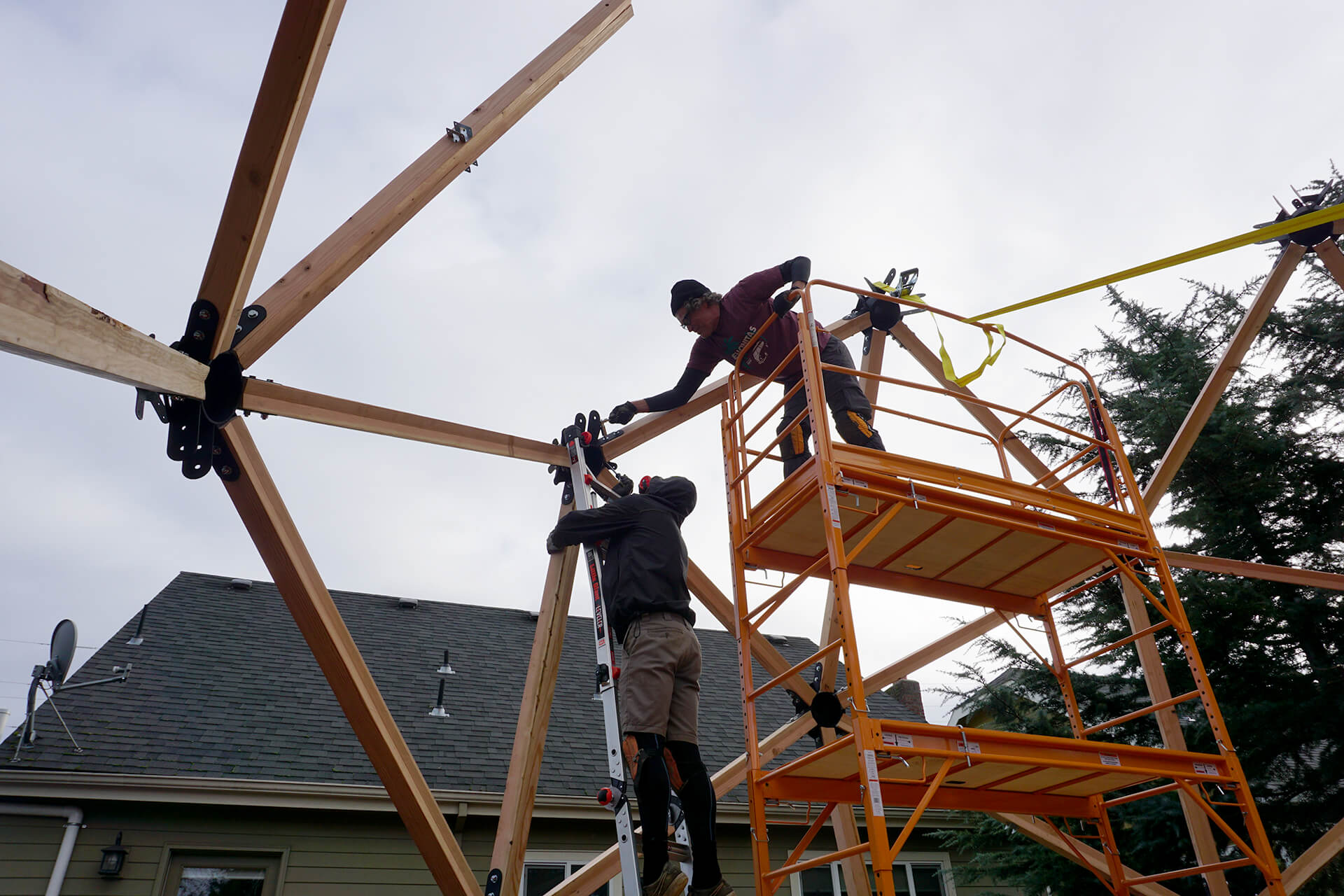
Use all necessary techniques to ensure proper alignment: ratchet strap, rubber mallet, and alignment pin.
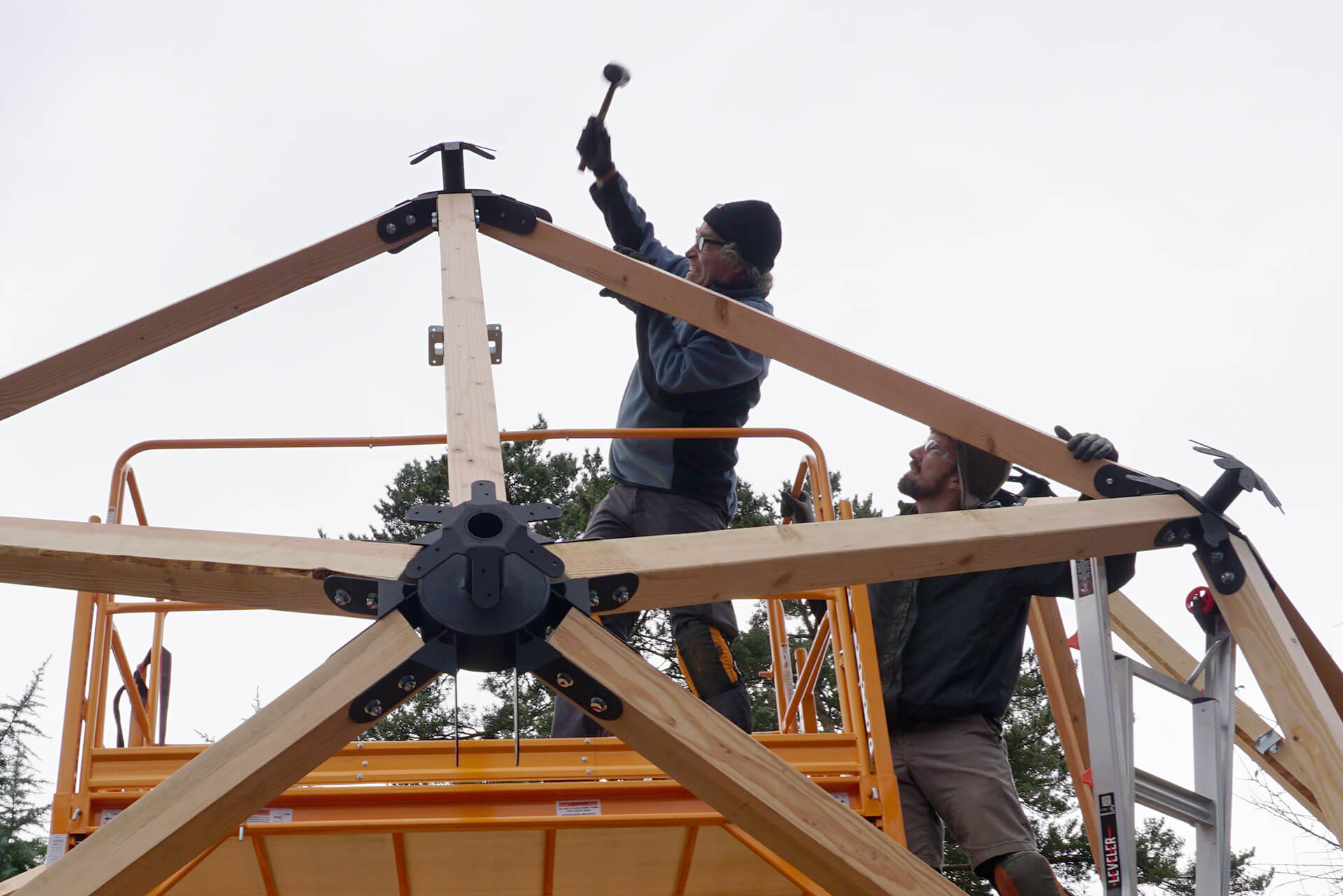
Repeat the steps of attaching individual components until another row of sections is completed. Then, torque and mark all fasteners.
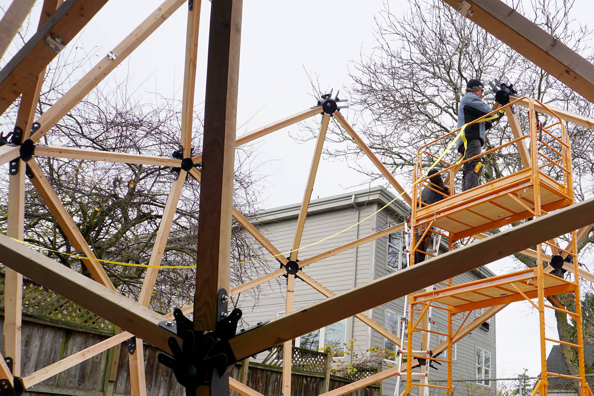
Use a ratchet strap across the dome to pull the structure into alignment if needed.
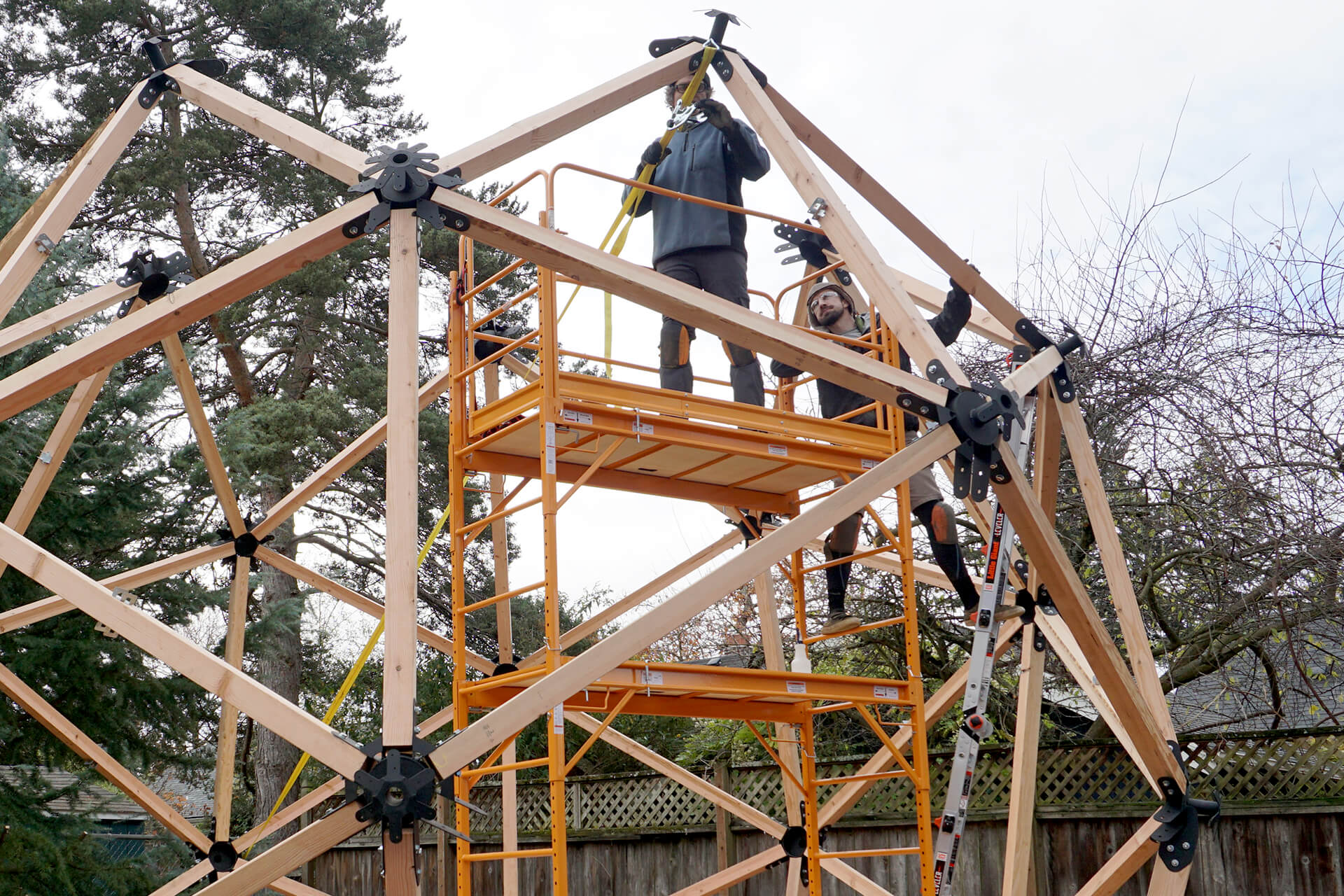
Attach Strut-Longs (not shown) between the existing steel Hubs to form the top pentagon (5-sides).
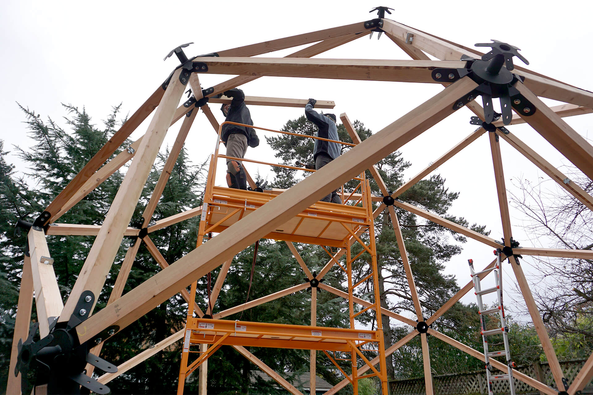
Attach two Strut-Shorts between the steel Hubs. Pick whichever two locations will fit easiest into the final Hub. Be prepared to change which two locations that is (see next photo).
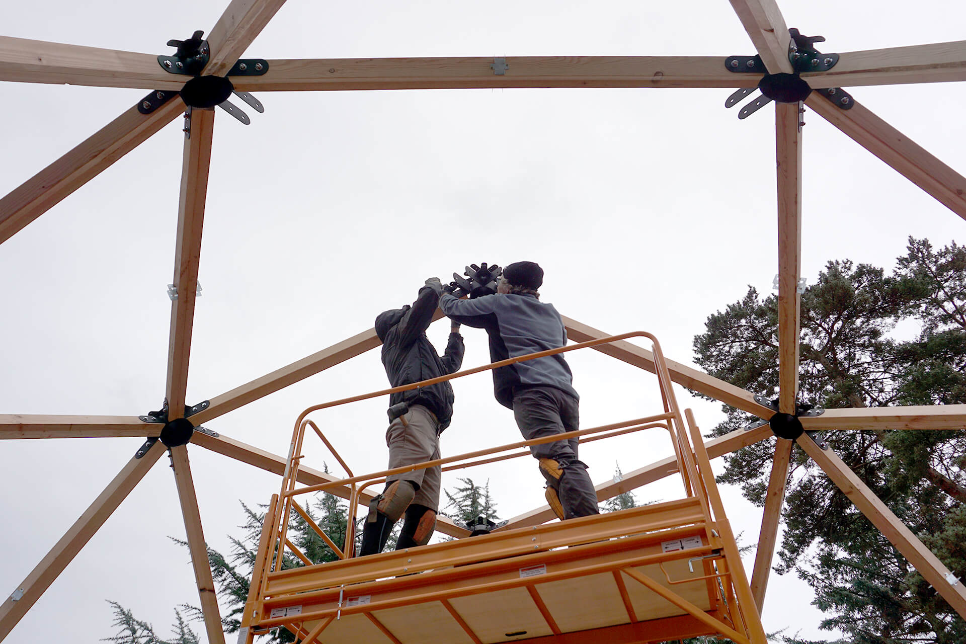
Attach the final steel Hub, followed by the remaining Strut-Shorts to complete the inner wall. Then, torque and mark all fasteners.
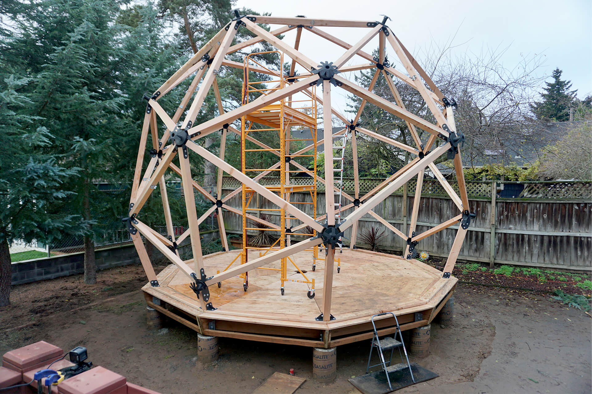
Congratulations on completing the inner wall! Make sure all fasteners are torqued and marked. They will need to be re-torqued at a later date because lumber shrinks as it dries out completely.
Next Step
© 2025 Dodeca Domes. All rights reserved.

