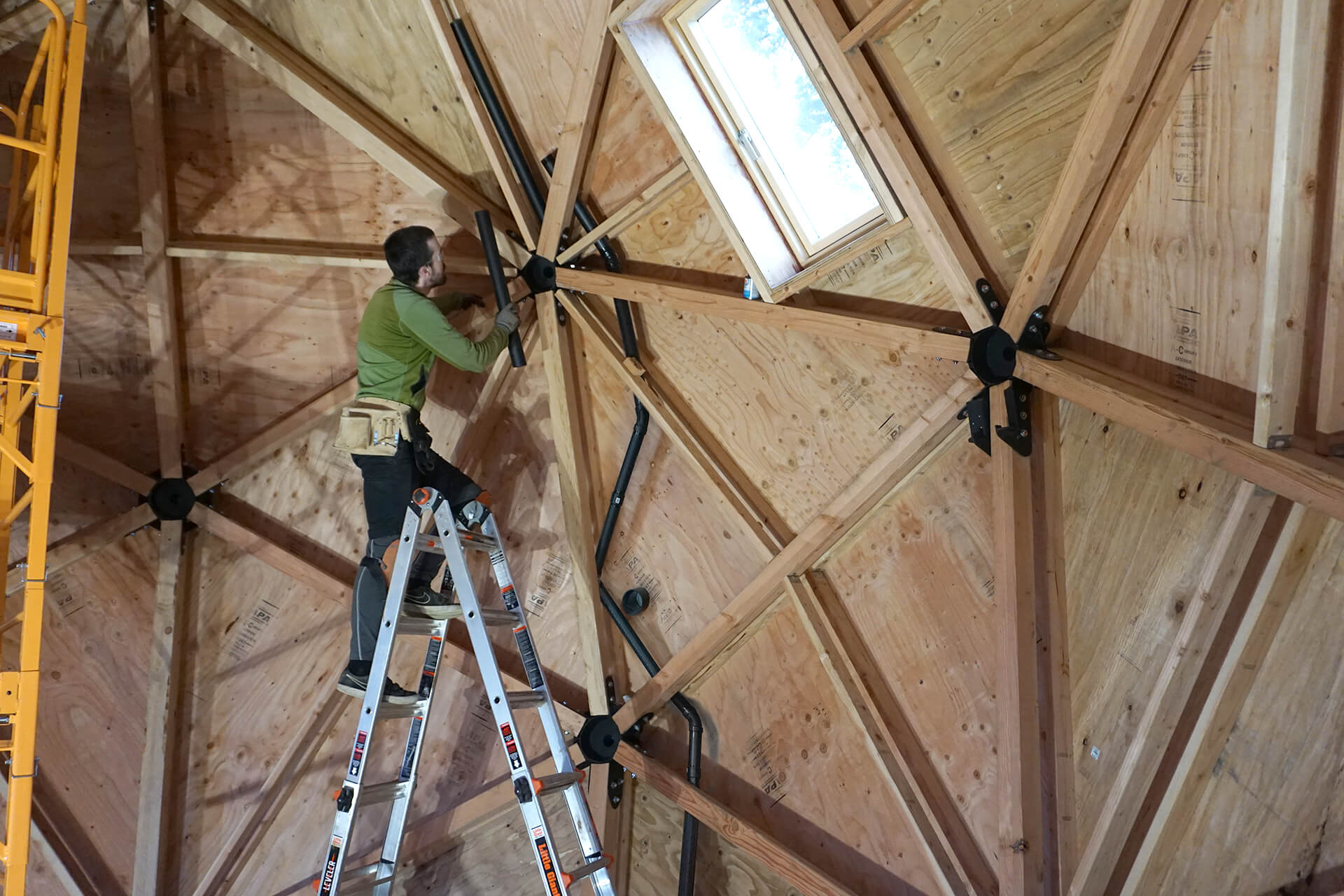
In-Wall – Vent Pipes
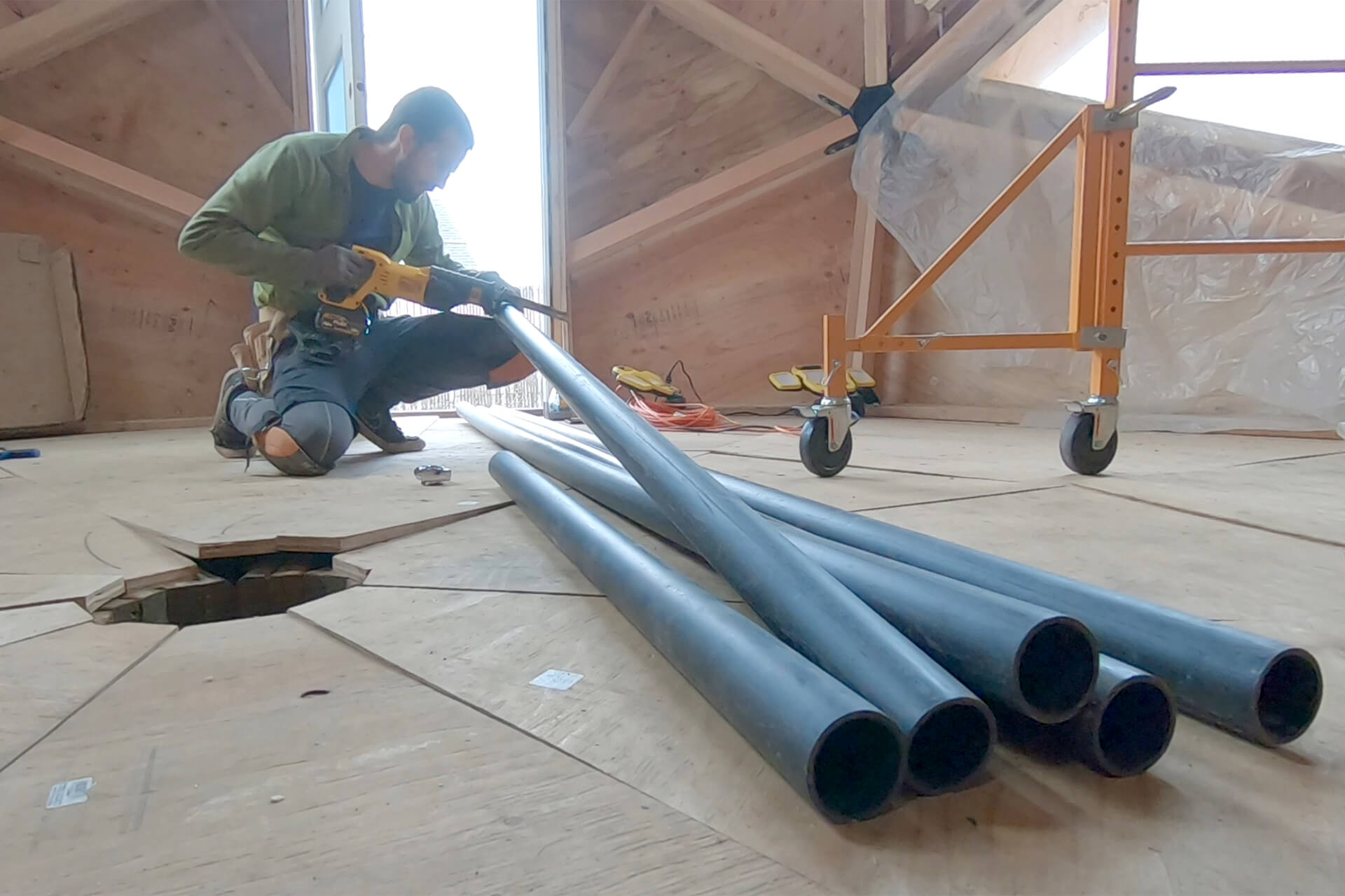
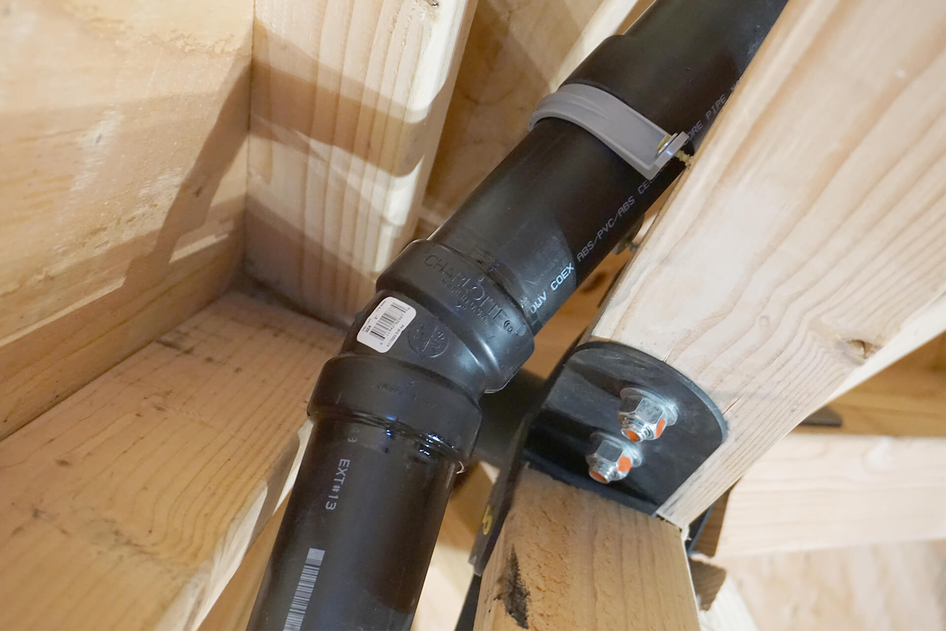
Use 2" Schedule 40 ABS pipe for the vents. Debur the inside of the pipe after each cut.
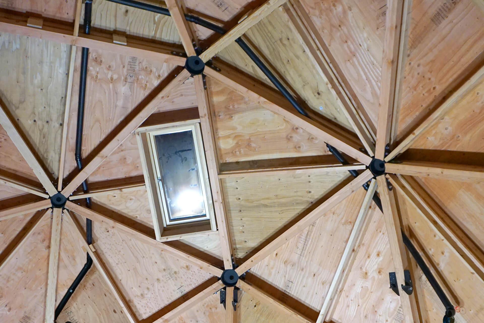
Extend the toilet vent pipe upward and around the HRV vent opening.
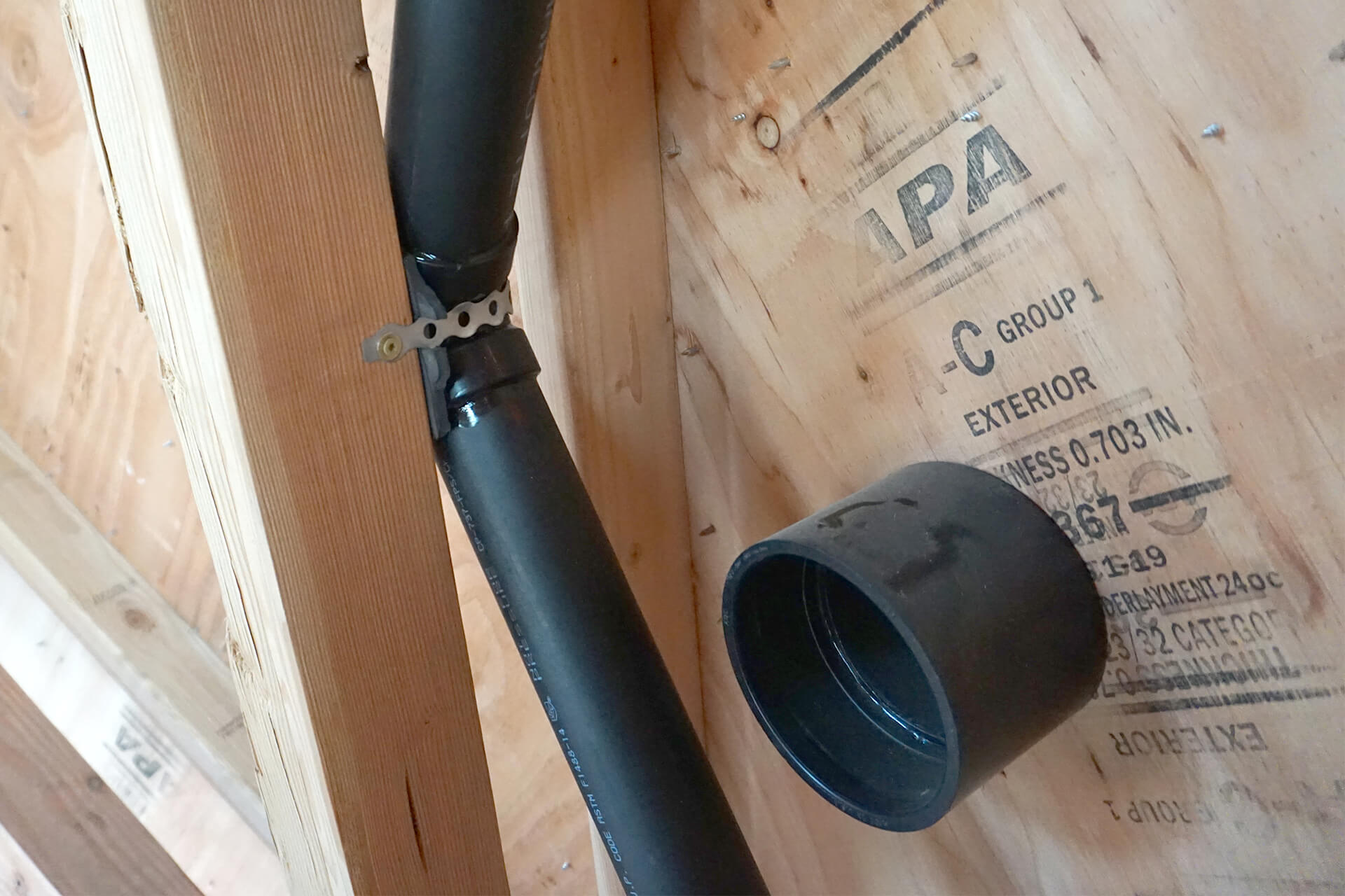
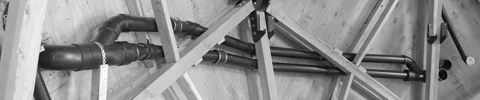
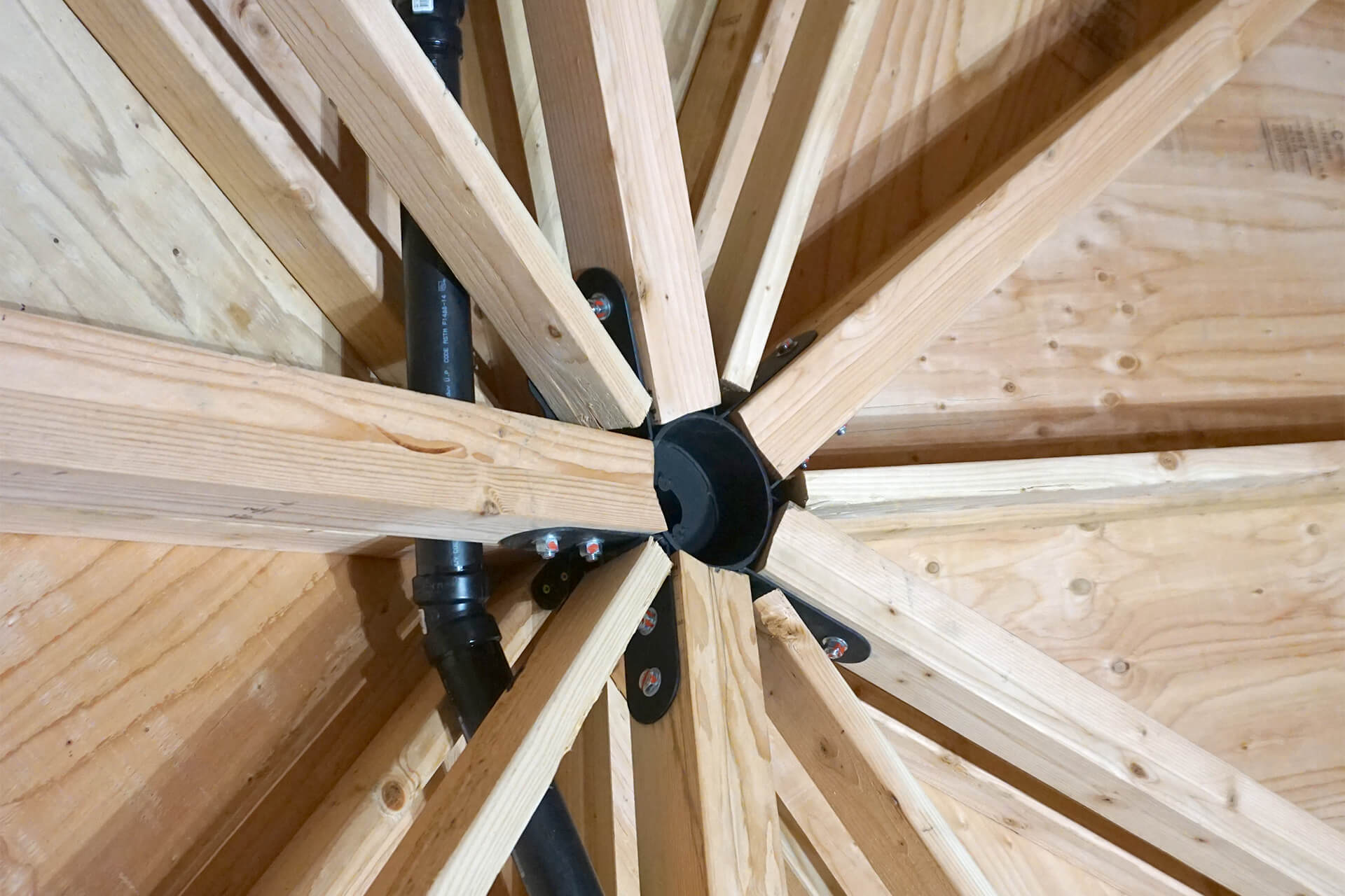
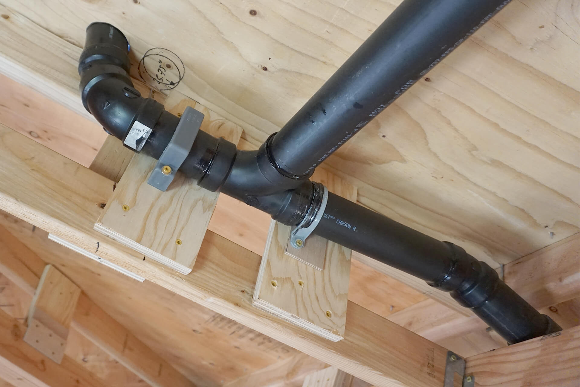
Use metal strapping (shown here) or pipe clamps to secure the pipe in place. Rubber or foam can also be used to ensure a snug, noise-free connection.
Continue routing the pipe upward, closer to the connection point where it will meet the other vent pipe just before exiting through the roof.
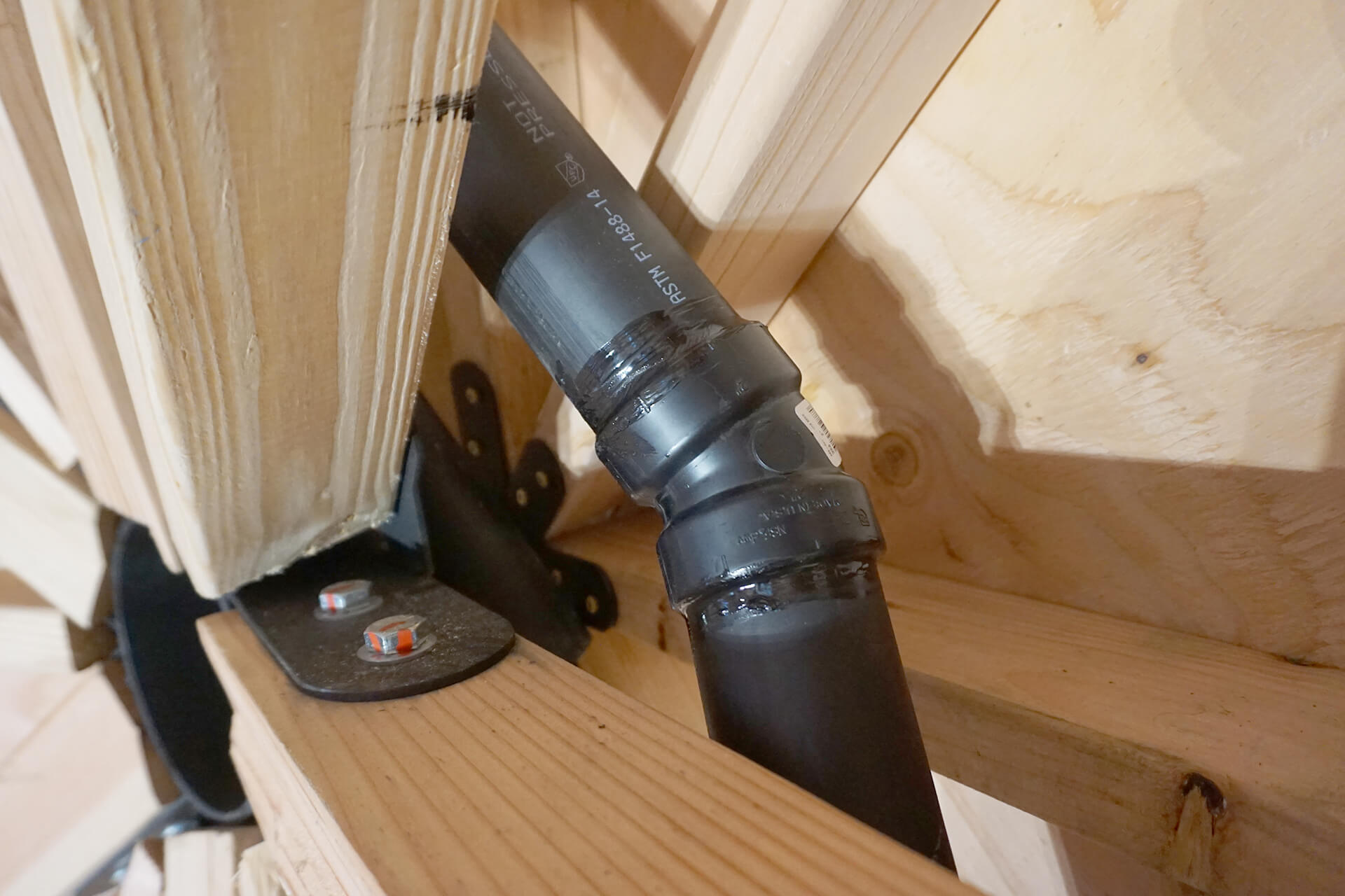
22.5-degree fittings are ideal for achieving some of the desired bends.
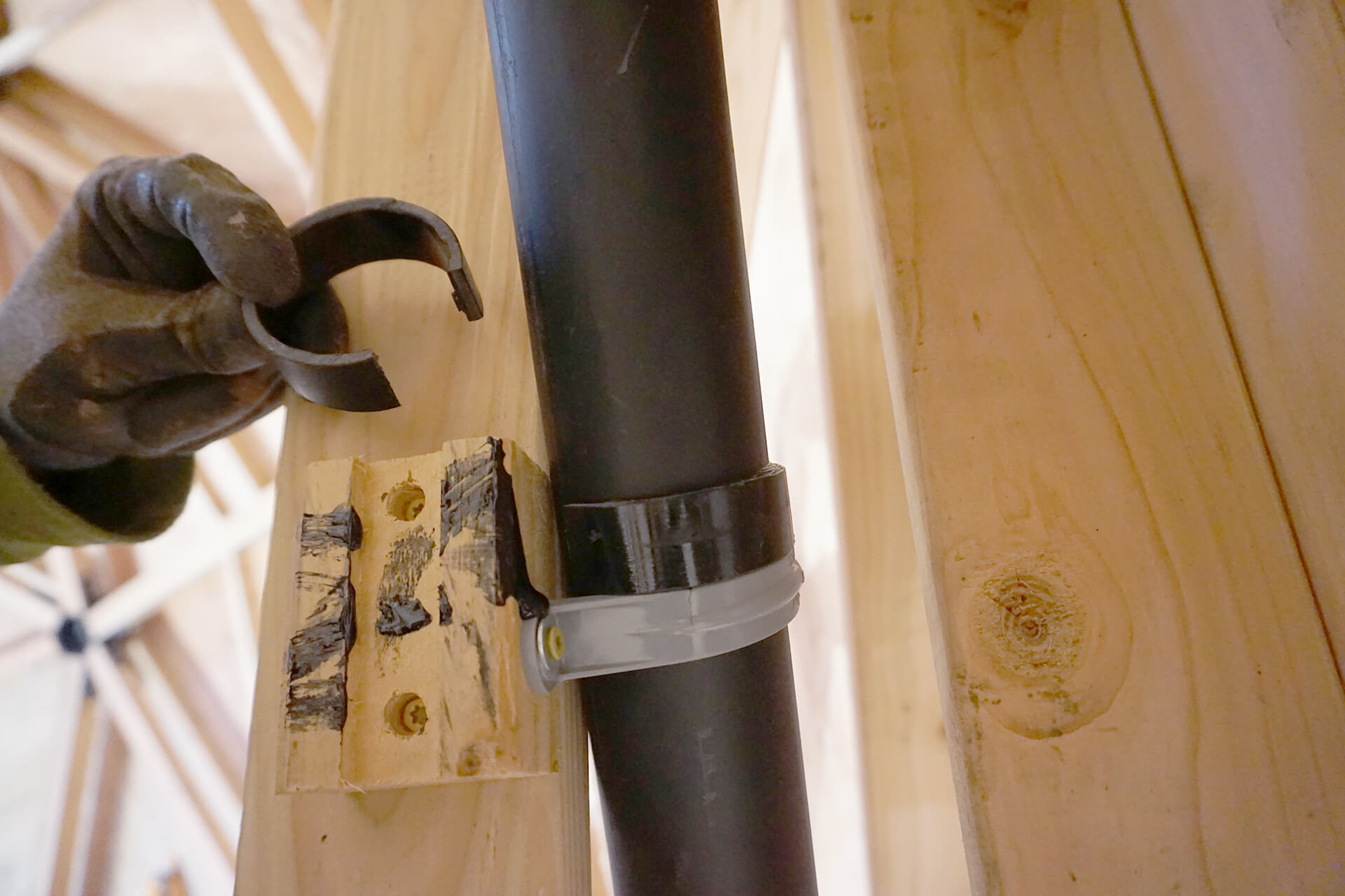
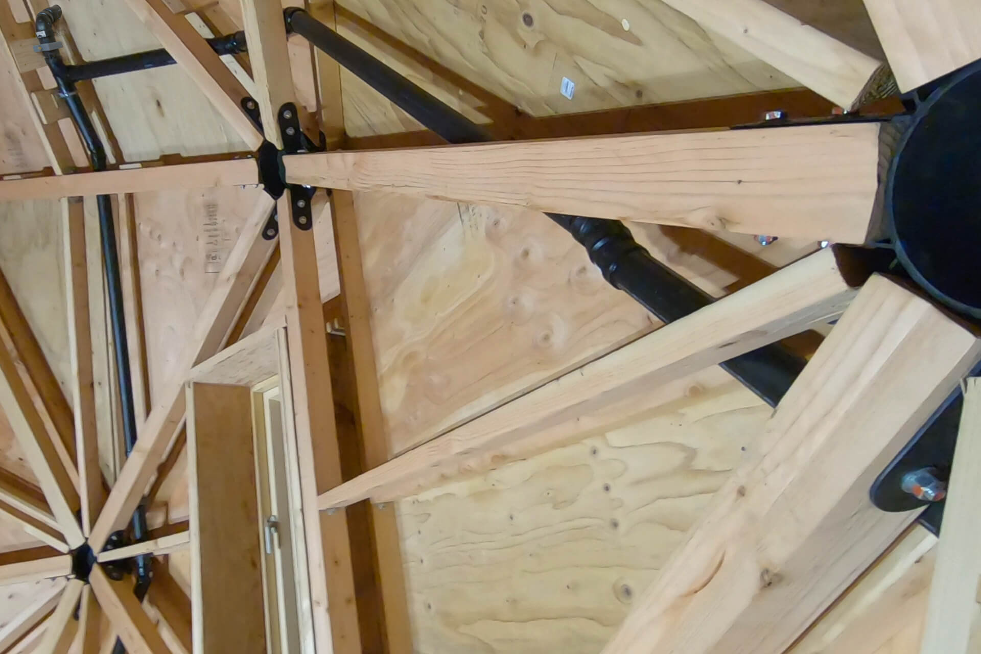
A C-clamp can be cut from scrap pipe and glued in place to create a lip for resting against a pipe clamp (shown here). Do not restrict movement too much to allow for thermal expansion.
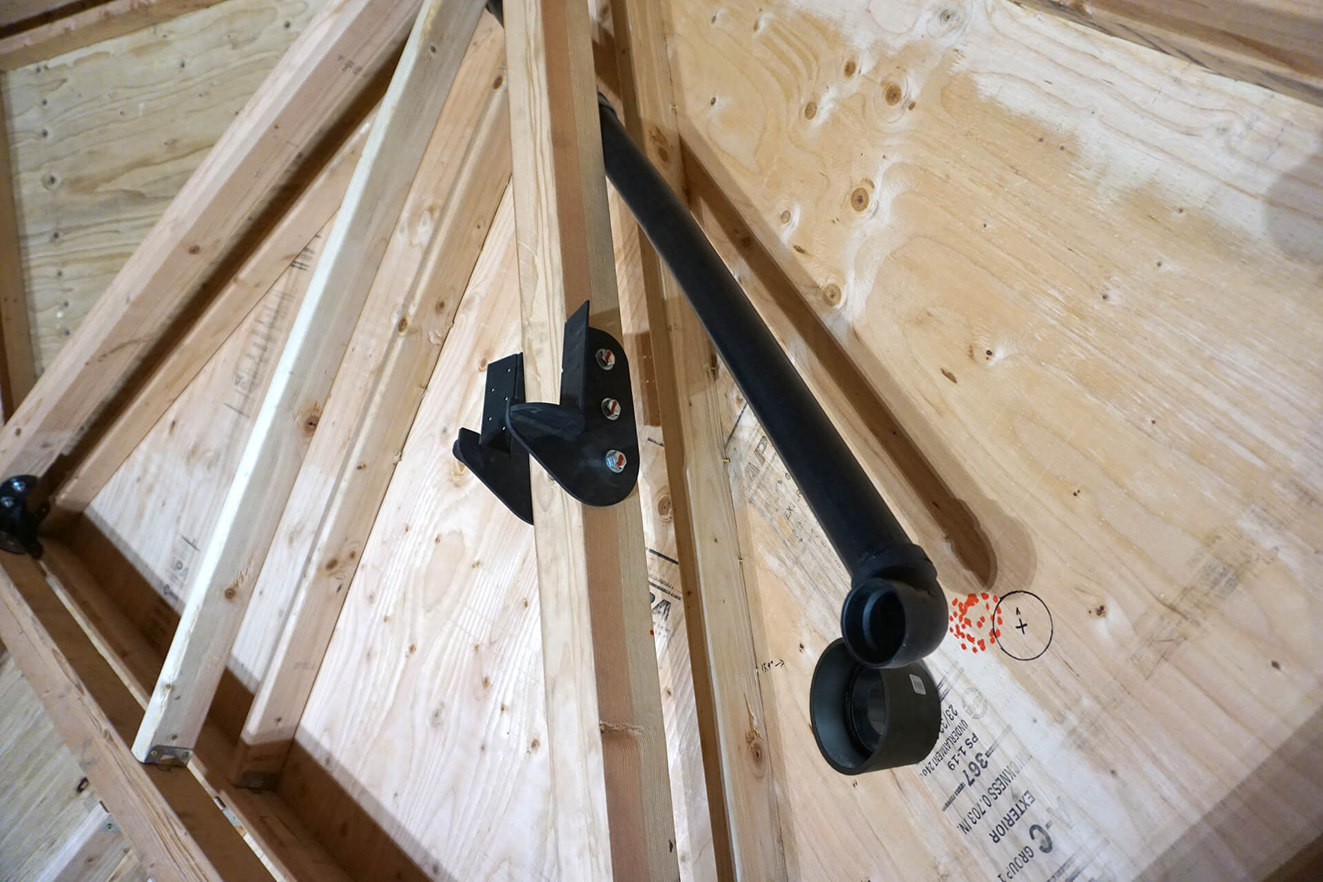
Mark the ideal location and begin routing the vent pipe that will eventually pass through the kitchenette wall.
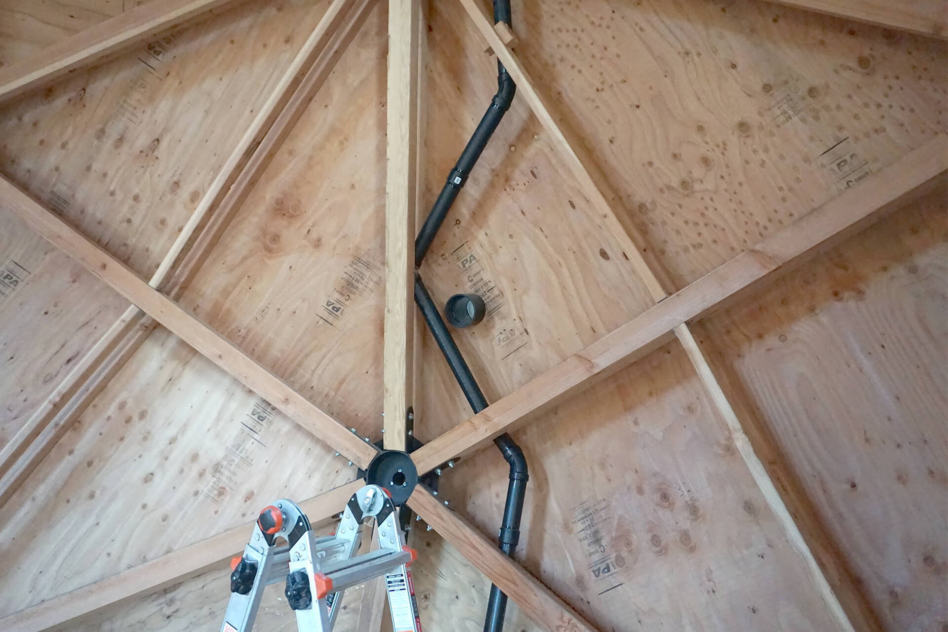
Routing the pipe upward, snaking it around various hubs.
Another 22.5-degree fitting is shown here, along with a C-clamp lip and pipe clamp attachment point.
Route the pipe over the Egress, where it will connect to the other vent.
All venting should fit cleanly between the double-wall gaps. No cutting of lumber is required.
Ensure the vent pipe connections are secure where they meet and exit through the roof.
Next Step