
Electrical – Boxes
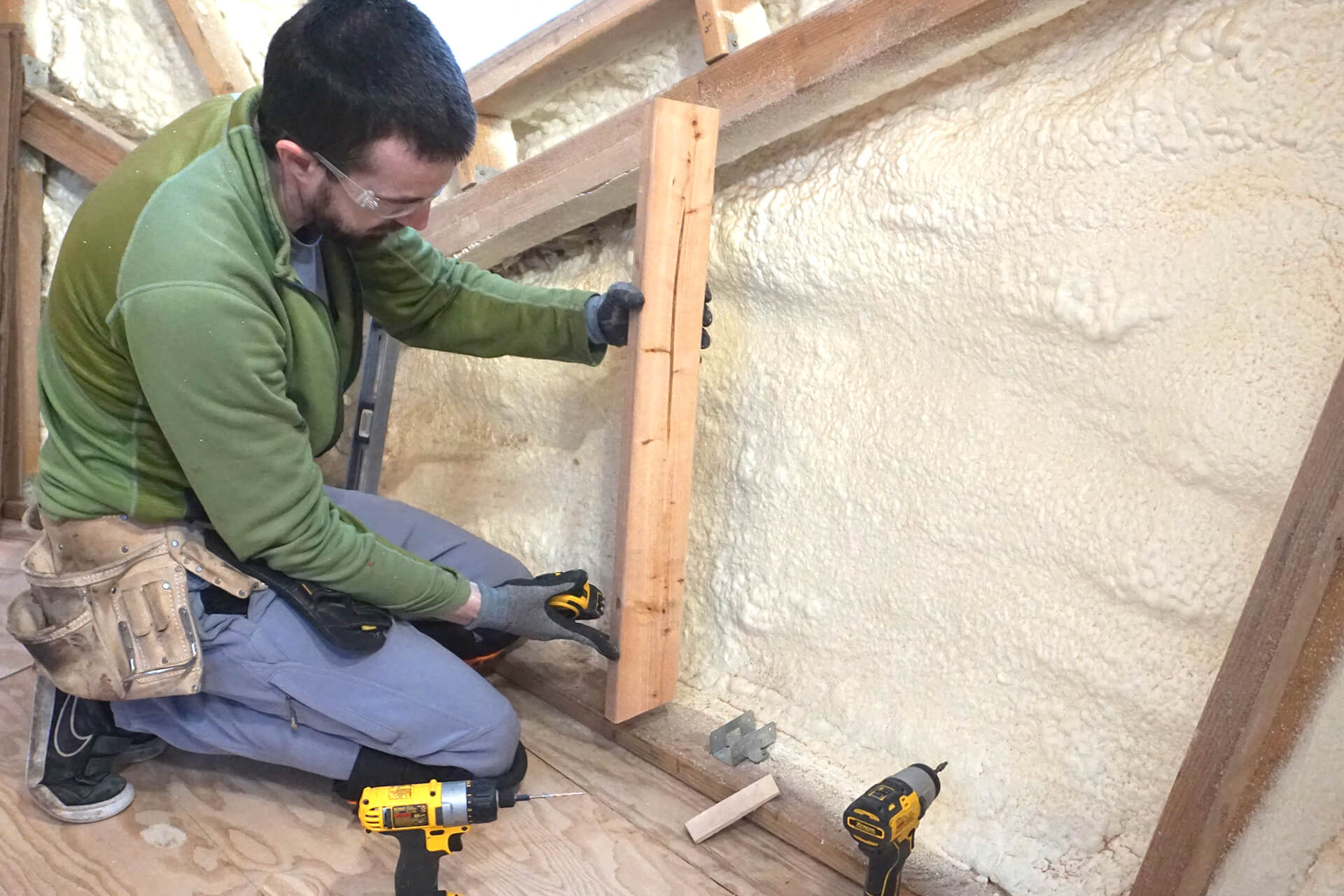
Install the Stud-Bases by first attaching the stud holders (Simpson RTR) towards the back of the Sill-Plate-Ins as shown. Shim the top of the Stud-Bases as needed.
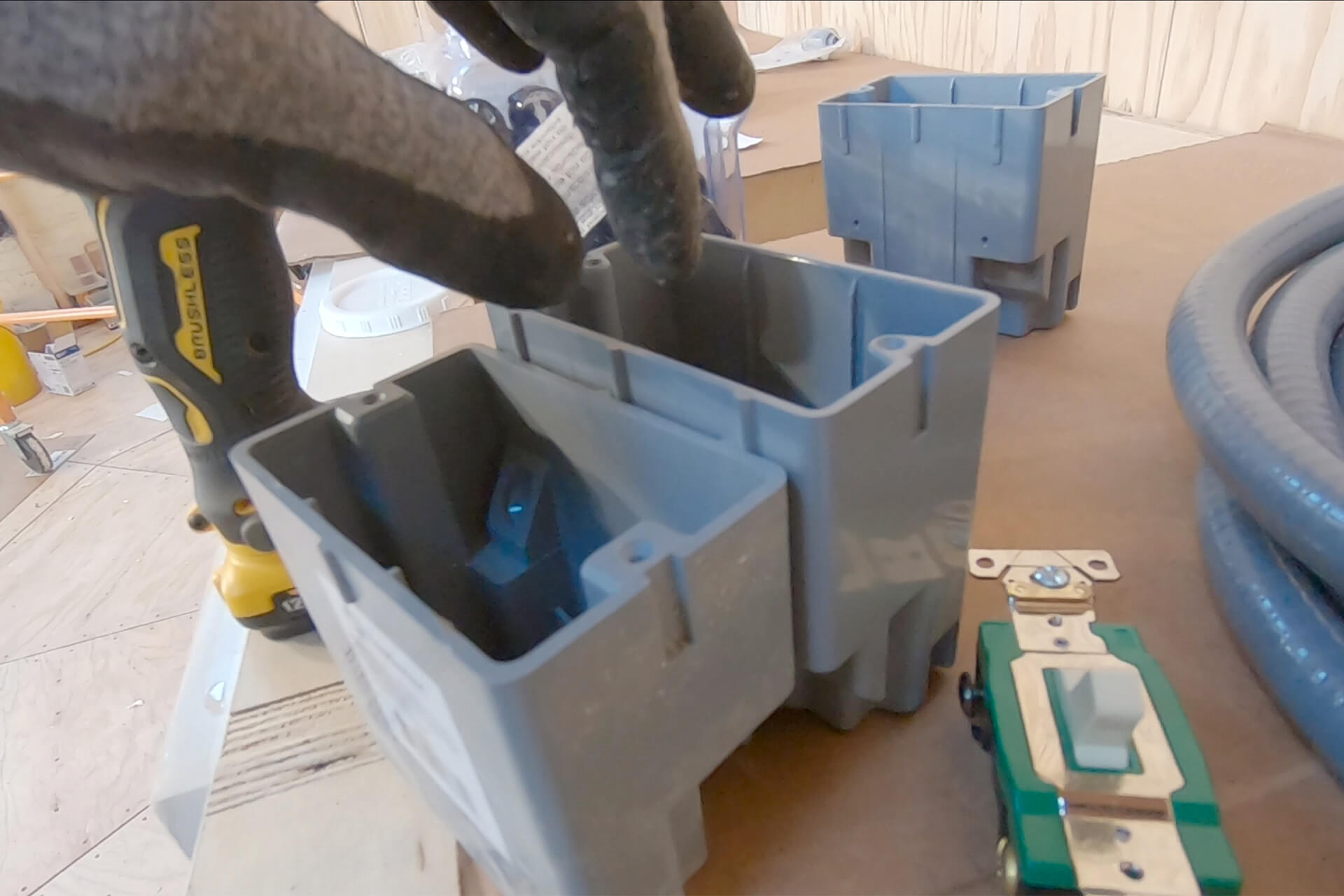
Deeper electrical boxes provide greater interior volume, allowing for more code-compliant box-fill options. Deep boxes support both Y-splicing and daisy-chaining of circuits.
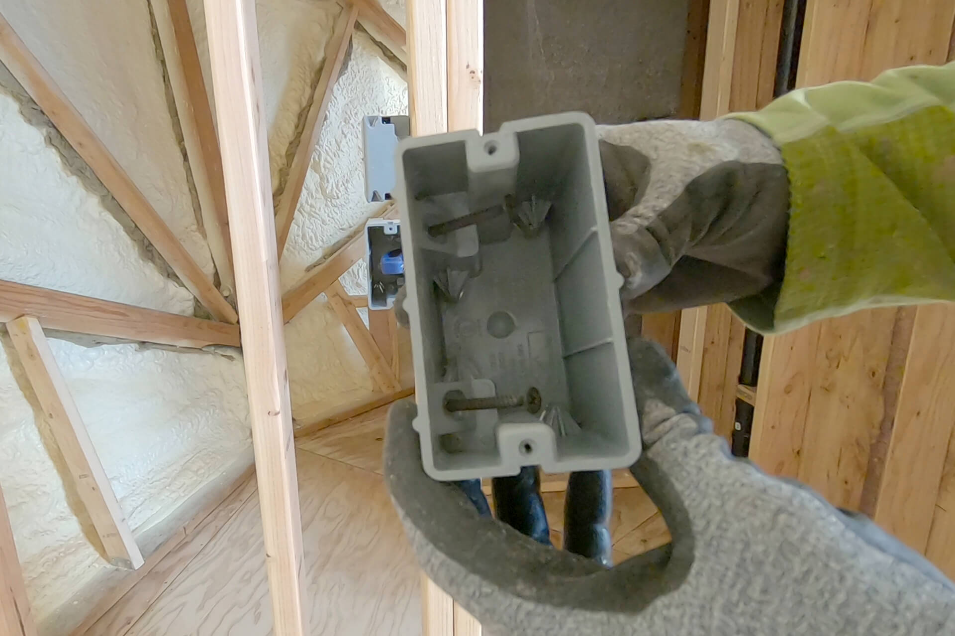
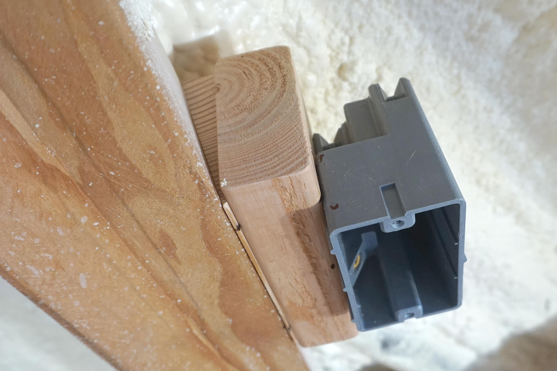
These electrical boxes have built-in screws for mounting. Optionally, replace them with equivalent torx-head screws for easier installation.
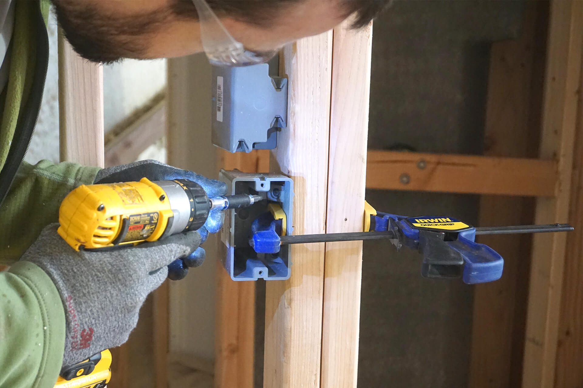
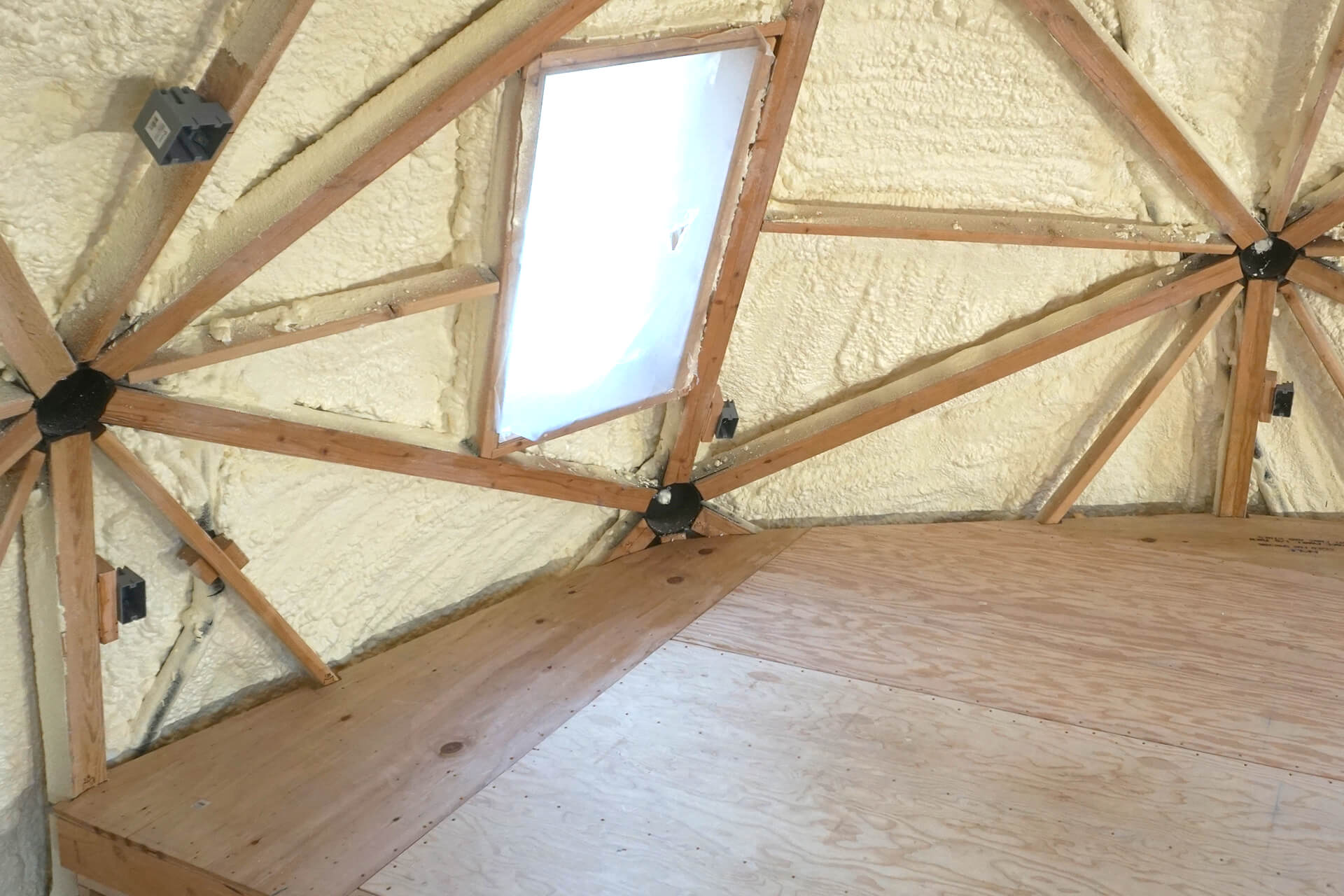
Clamp the electrical boxes proud of the studs so they will sit flush with future wall coverings, except for the thermostat and microwave box, which will sit just behind the wall covering.
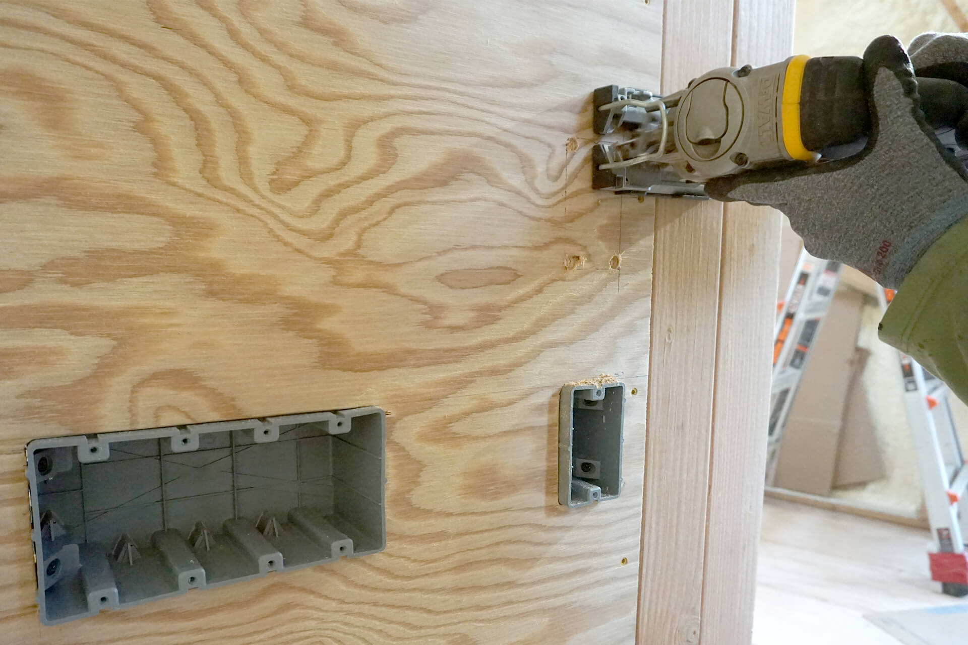
Drill corner holes and use a jigsaw to cut precise electrical box openings in plywood. When a box can’t be clamped, account for pull-through when tightening down the screws.
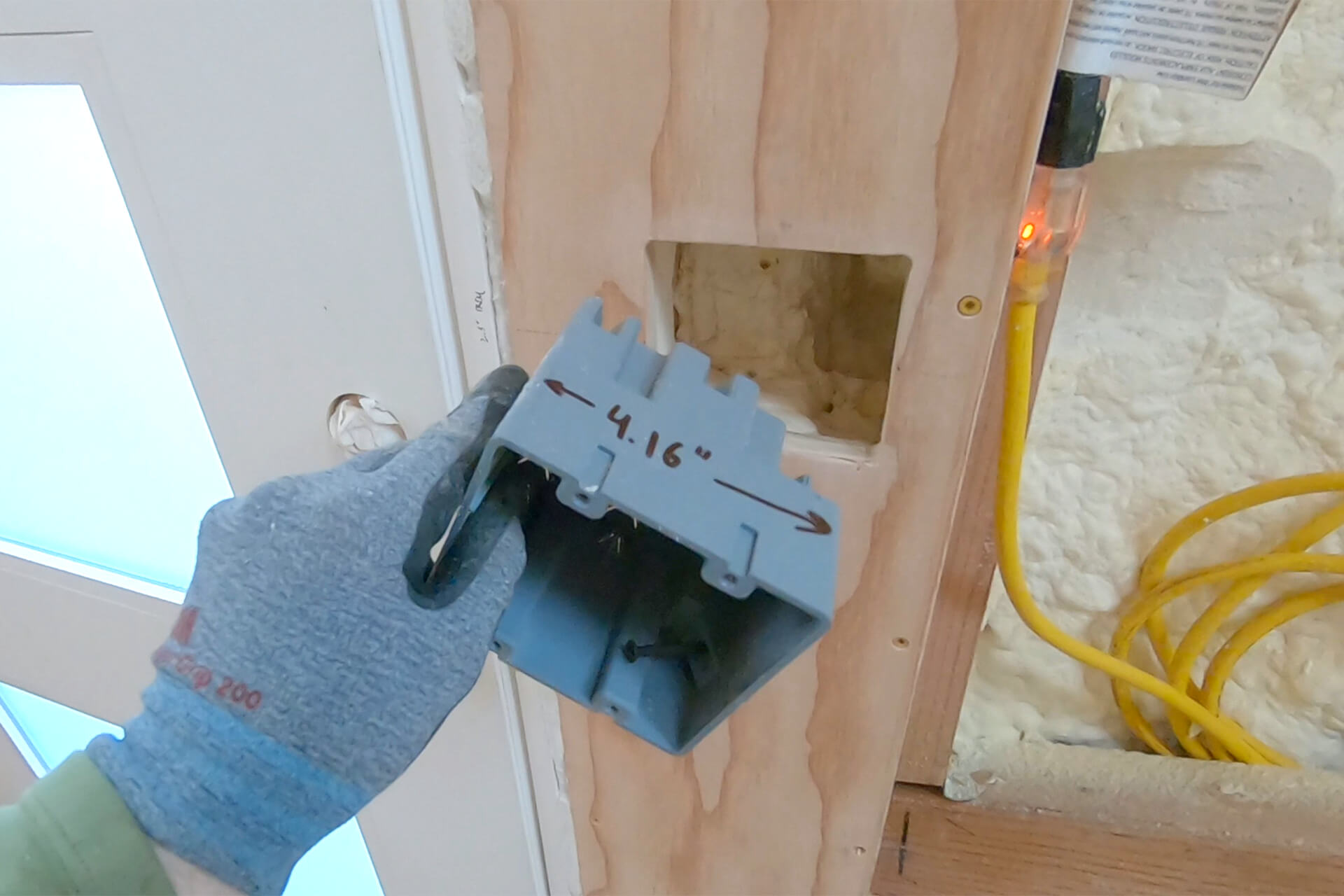
Cut the opening and carve out the foam for the electrical box and future wiring near the front door. Place the box, but do not secure it until the wires have been run through.
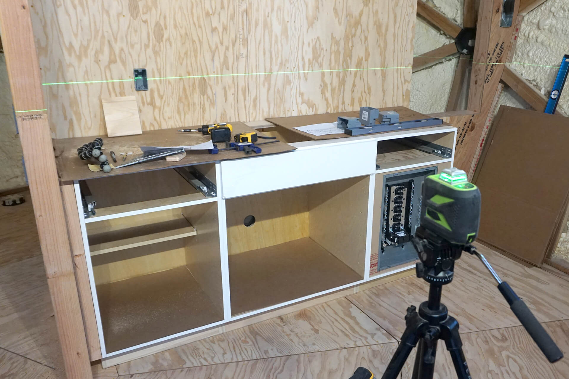
Use a laser to mark the locations for the electrical boxes.
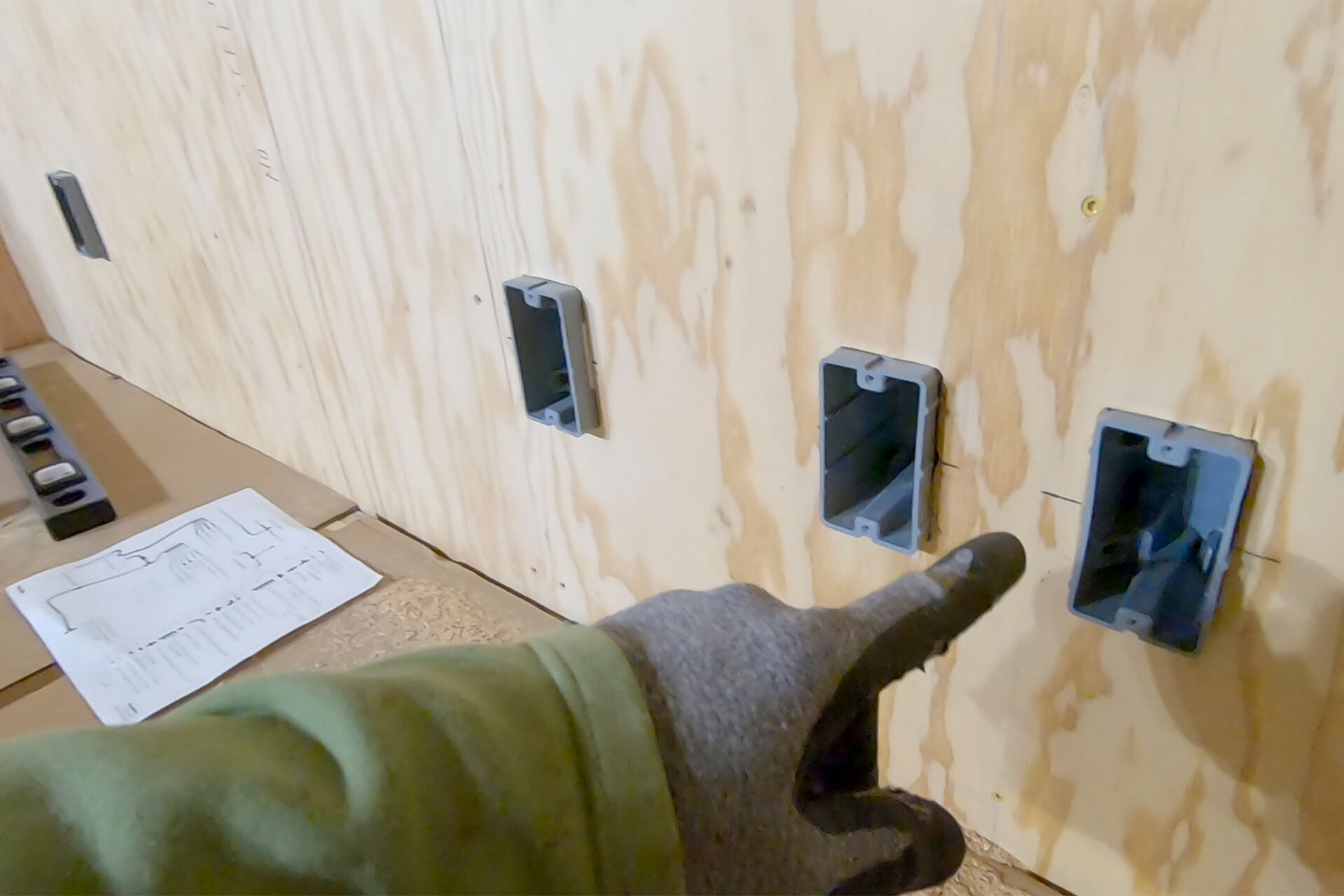
Mount the electrical boxes proud of the plywood so they sit flush with the future wall covering. The microwave electrical box (not shown) should be mounted flush with the plywood.
Continue installing electrical boxes. Mount the round smoke alarm box (not shown) in the ceiling above the egress window.
Upper floor electrical outlet boxes and the smoke alarm box (not shown) require spacers and shims to ensure proper clearance from corners and alignment with future wall coverings.
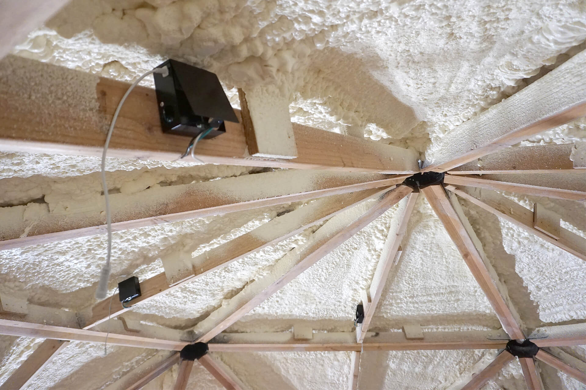
Install the junction boxes for the canless lights.
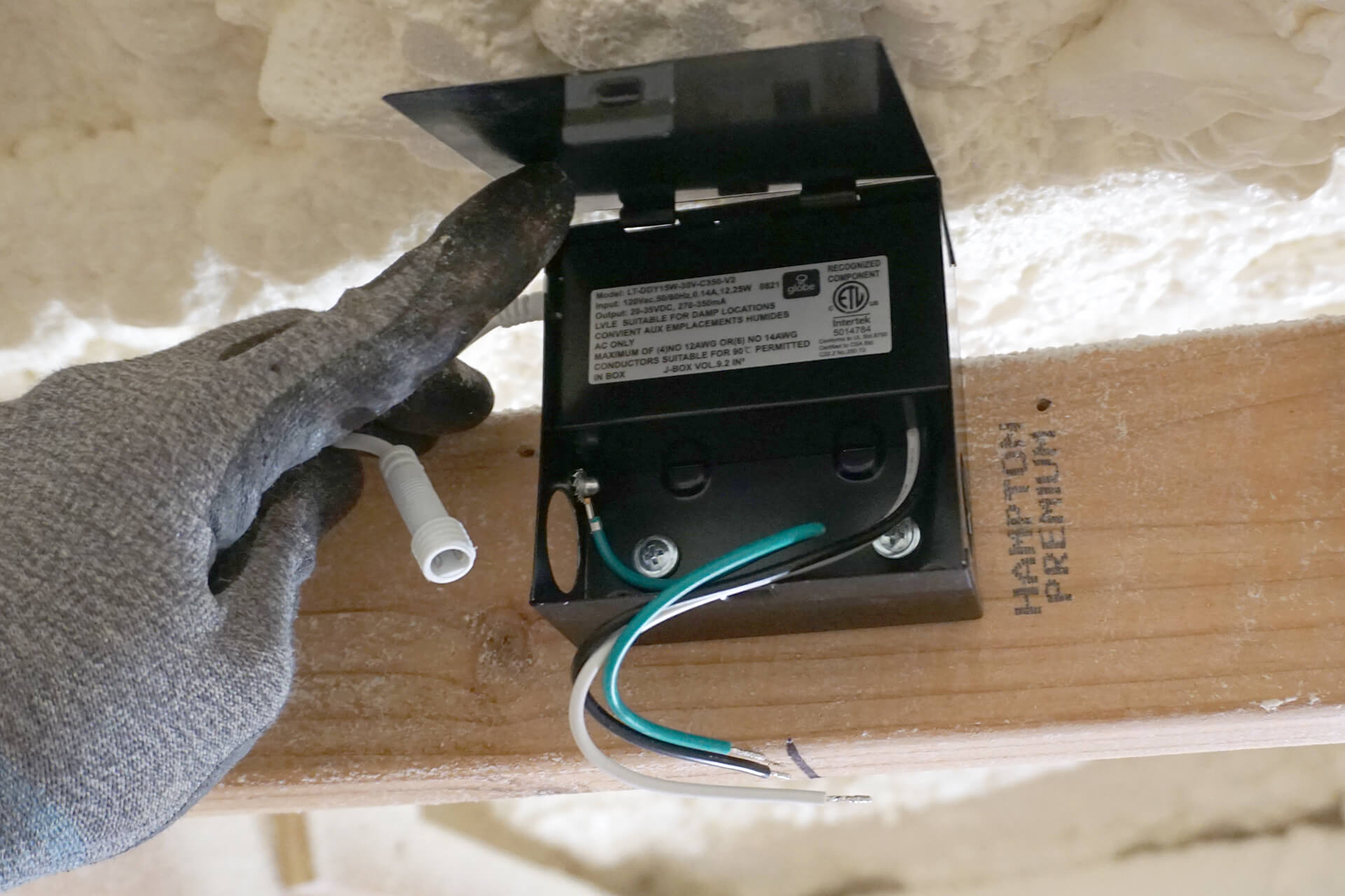
It may be necessary to cut or loosen the mounting screws in the future when replacing the light, so ensure the box is centered above the future ceiling hole for easy access.
Next Step