Plumbing
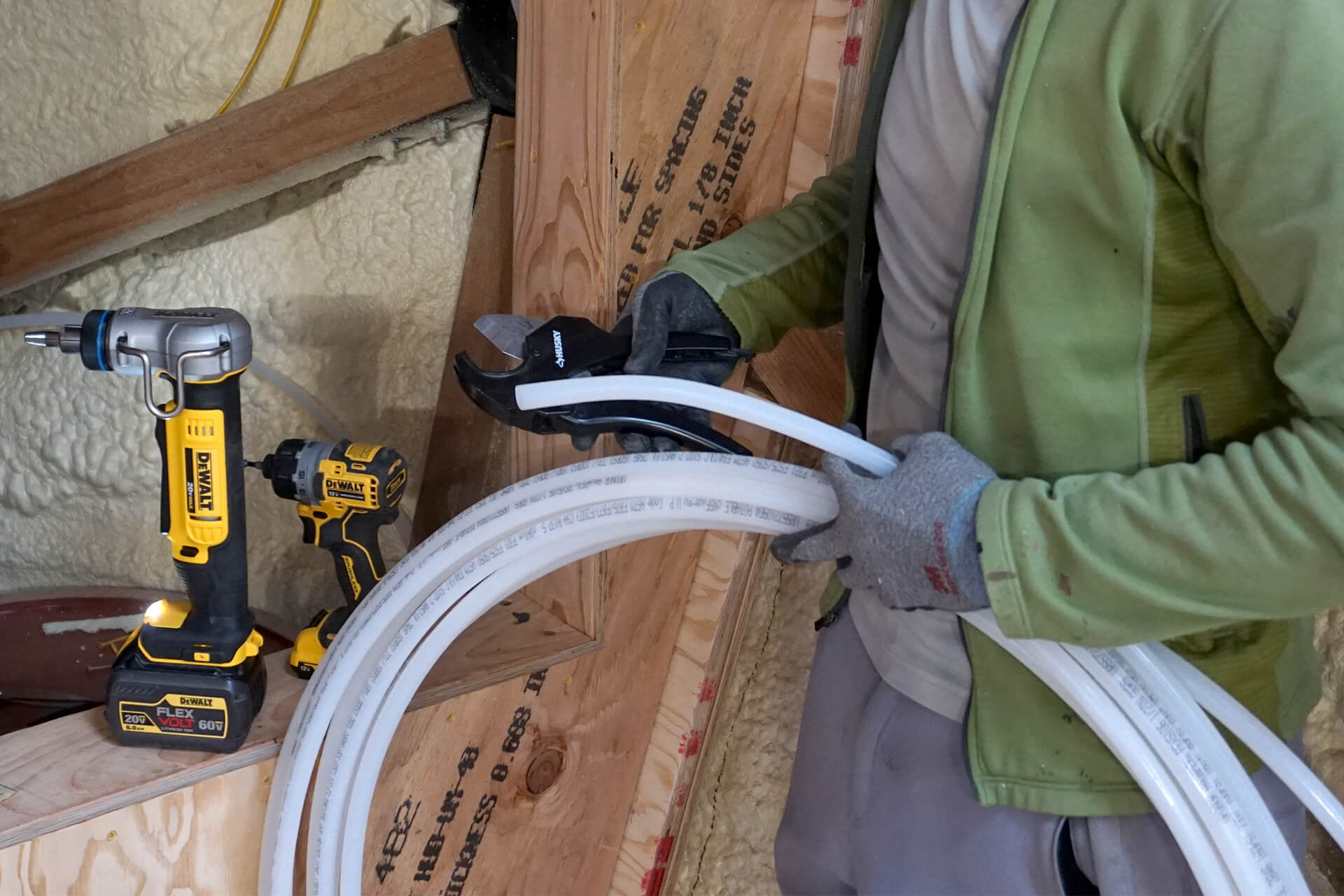
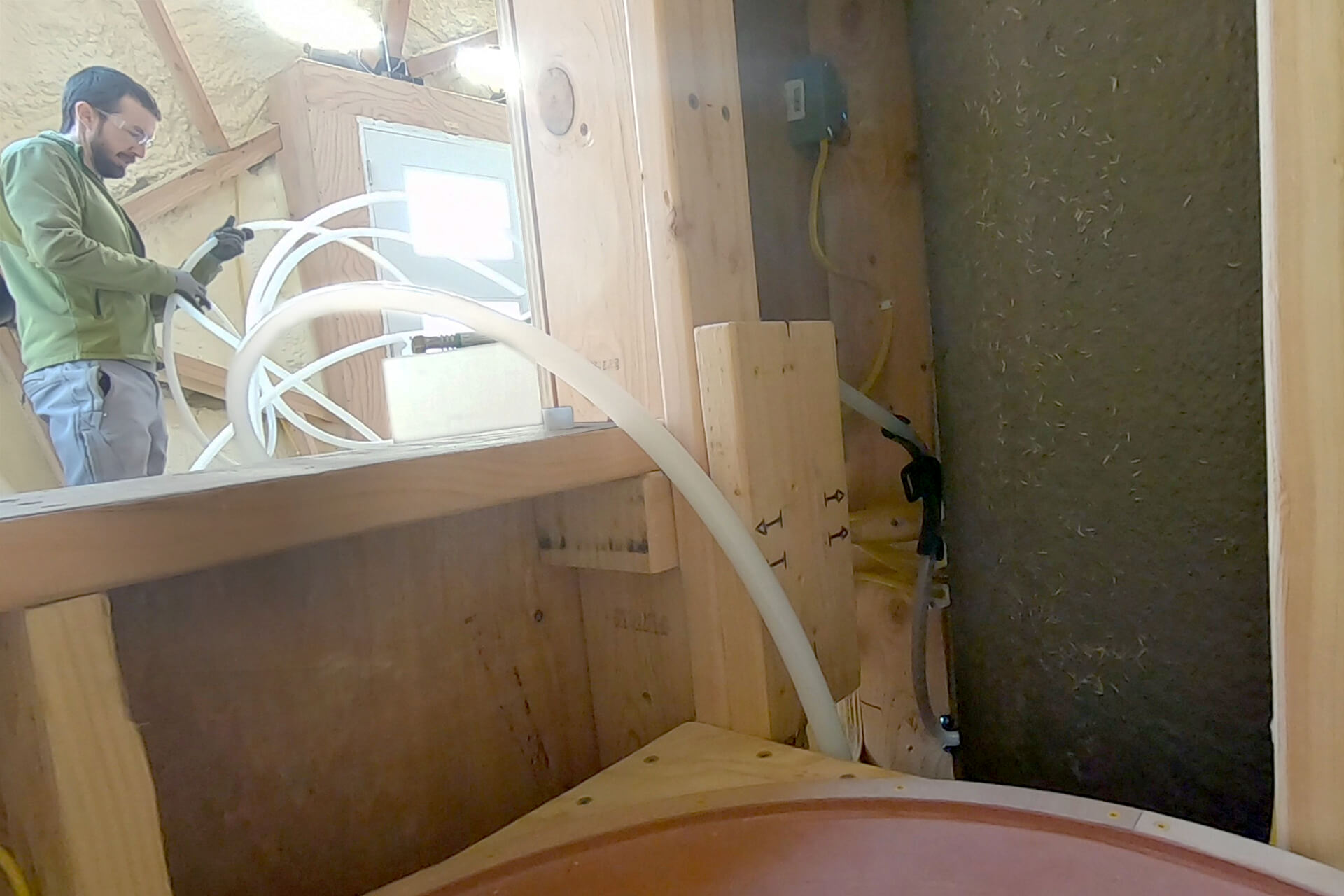
Loosen and enlarge the expansion PEX coils to make them easier to work with. Use a tube cutter for clean, accurate cuts. Uponor white 1/2” AquaPEX shown here.
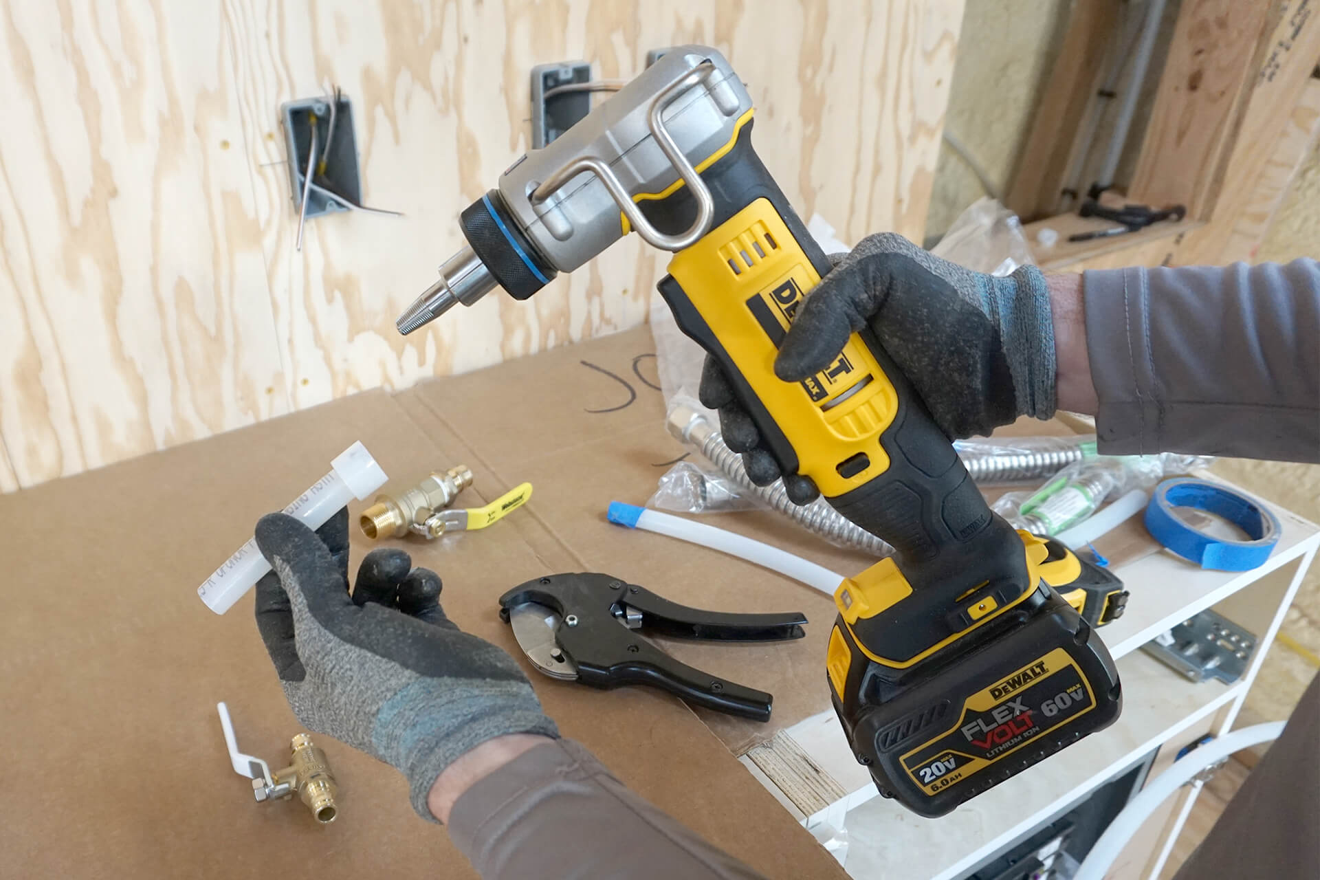
Become familiar with the expansion PEX tool and fitting installation process. Ensure the expansion ring is fully seated on the tube and does not shift during tool use or fitting install.
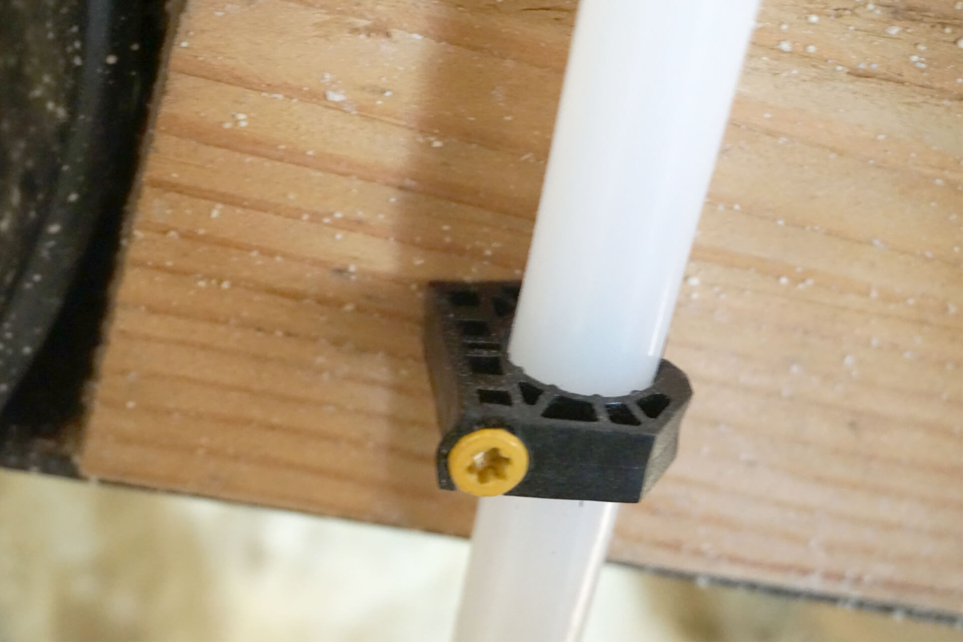
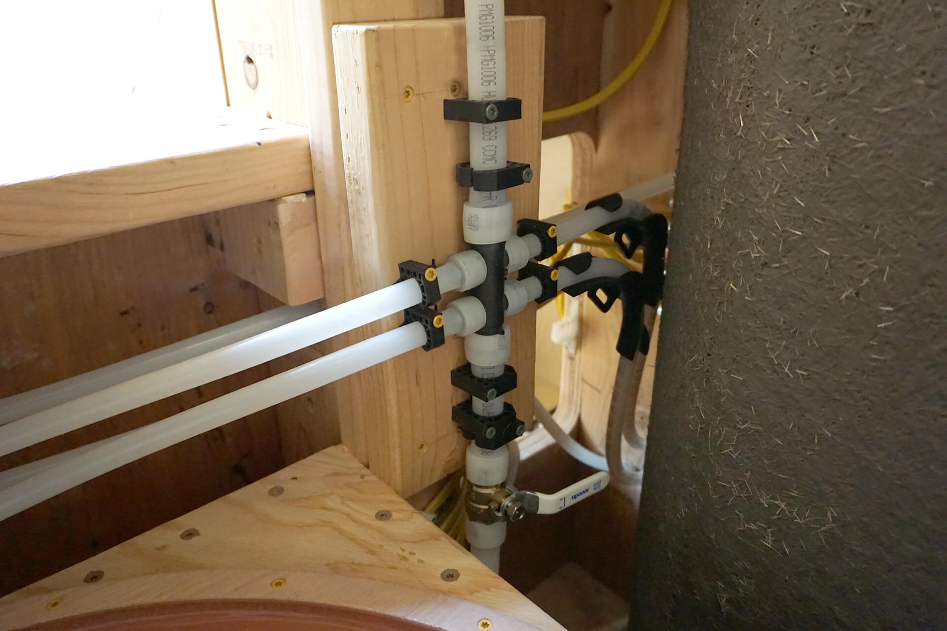
Use plastic clamps to secure the tubing. Optional: Replace the clamp’s nail with a properly sized wood screw (shown here) that doesn’t allow the threads to contact the tubing.
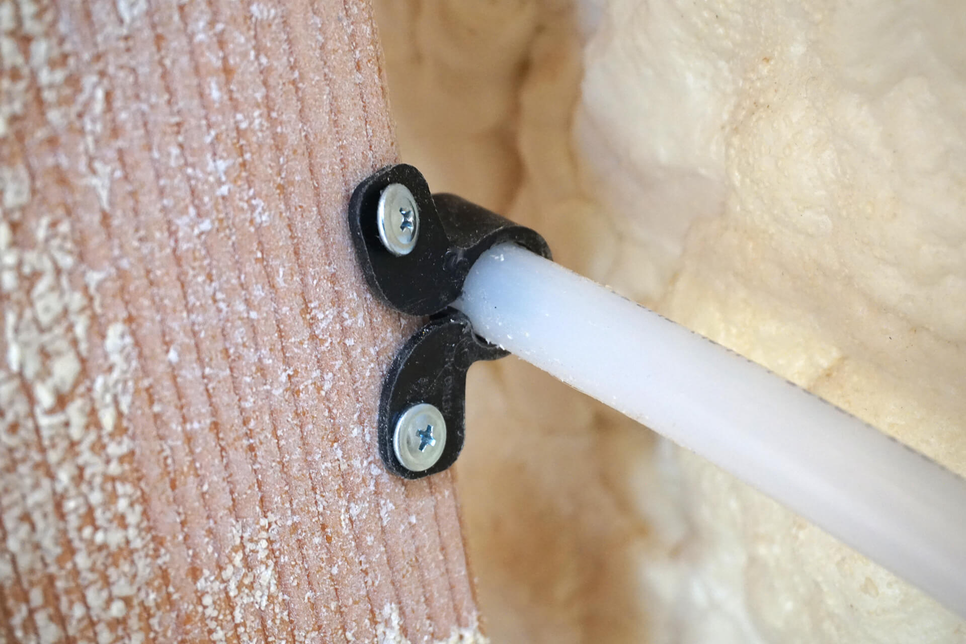
Use plastic clamps with wings to secure the tubing to hard-to-reach surfaces.
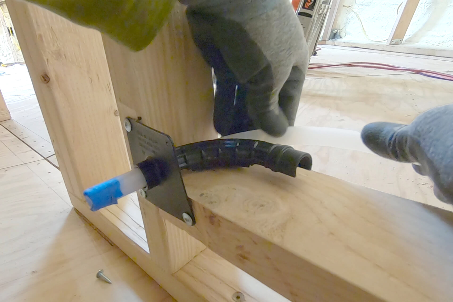
Use plastic bend supports to make tight turns with the tubing. These help prevent kinks and eliminate the need for elbow fittings, which can restrict flow and be a potential leak point.
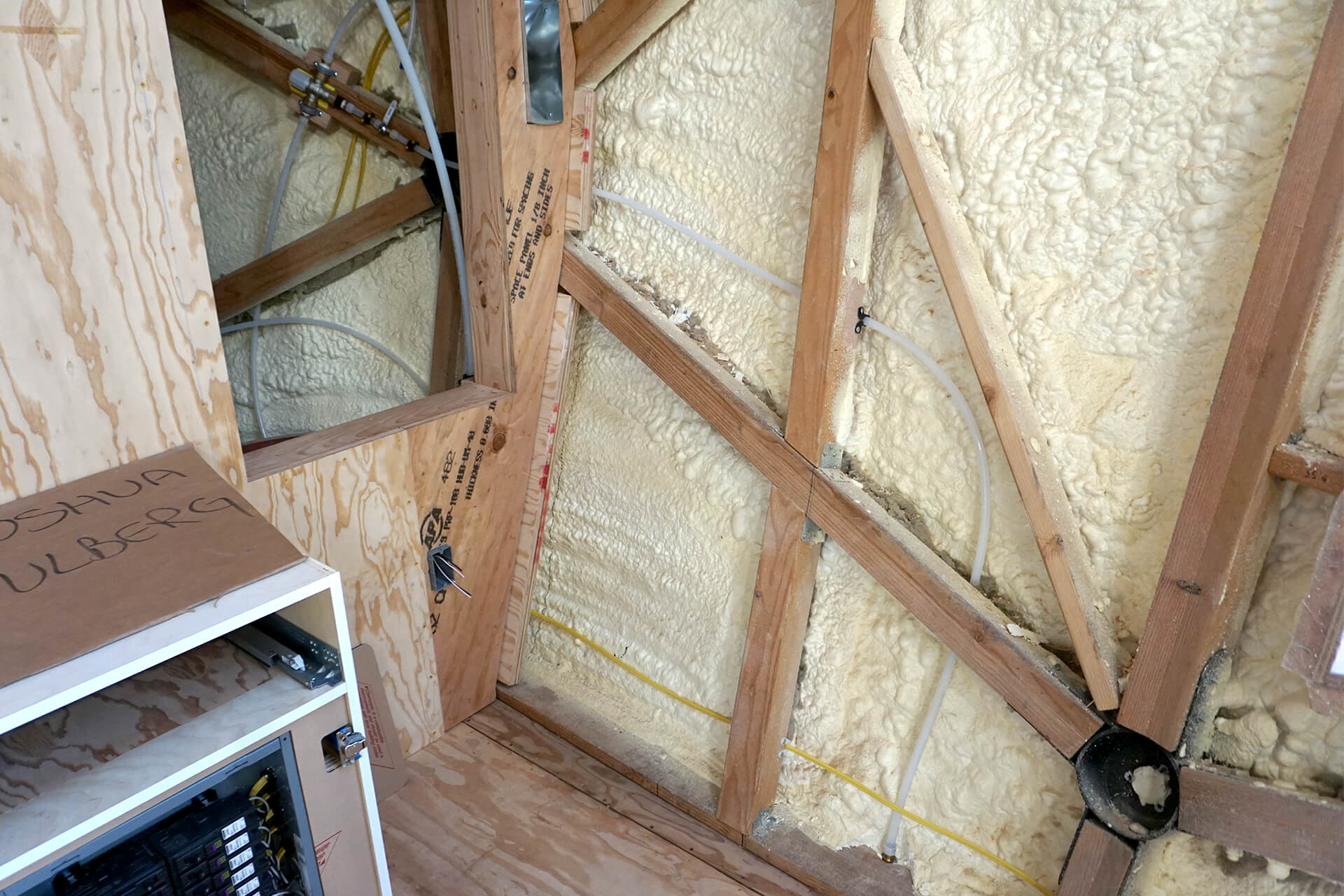
Feed the larger diameter (3/4”) PEX through the underground conduit that connects to the water source. This line will supply water to the dome.
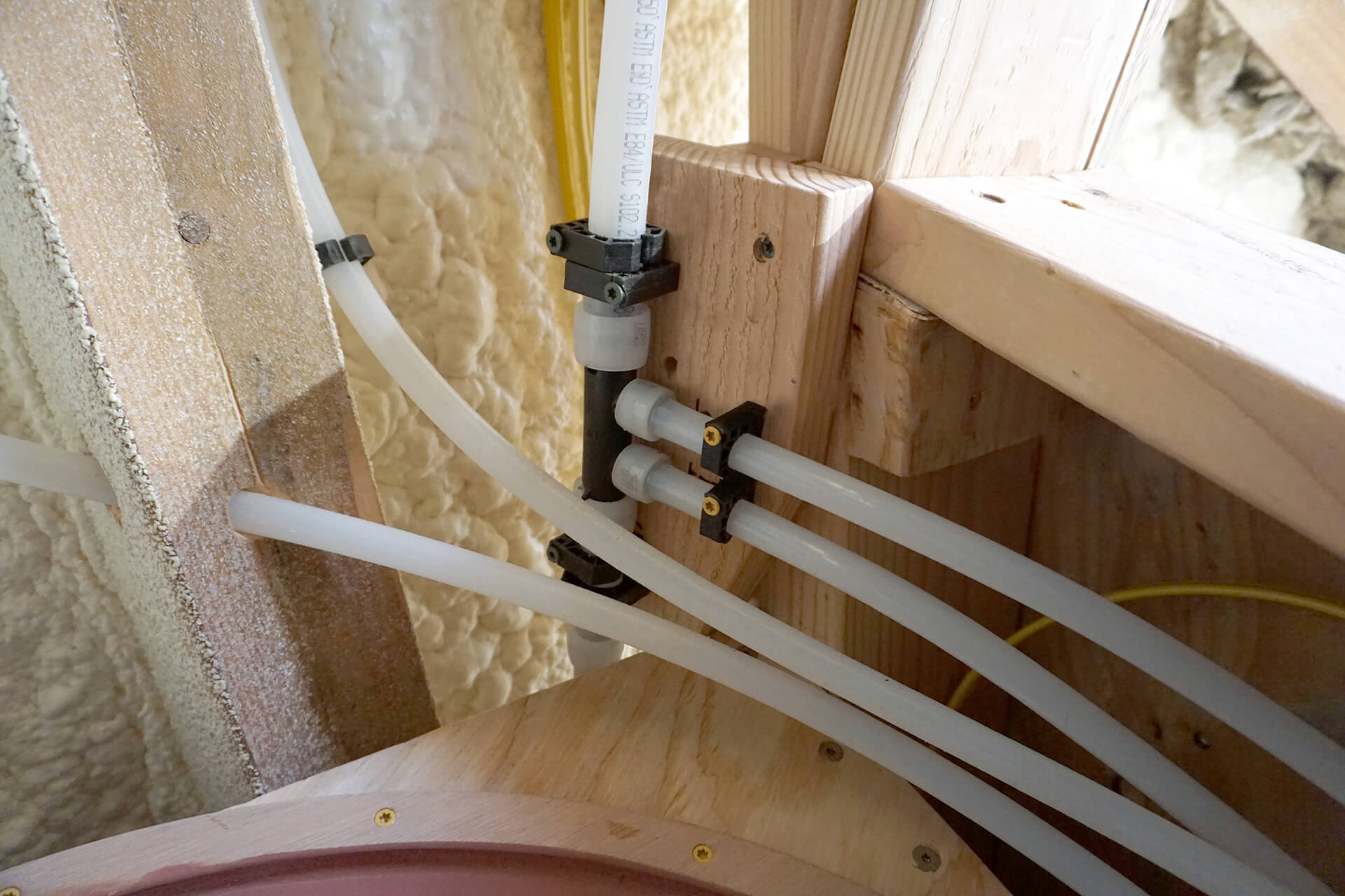
Install blocking, the main shut-off valve, and the multi-port manifolds (cold-water manifold shown here). The large diameter top tube will connect to the future water heater.
Plumb the shower valve and drop ear. Use the smaller diameter (1/2”) tubing for the home-run connections between the multi-port manifolds and the dome fixtures.
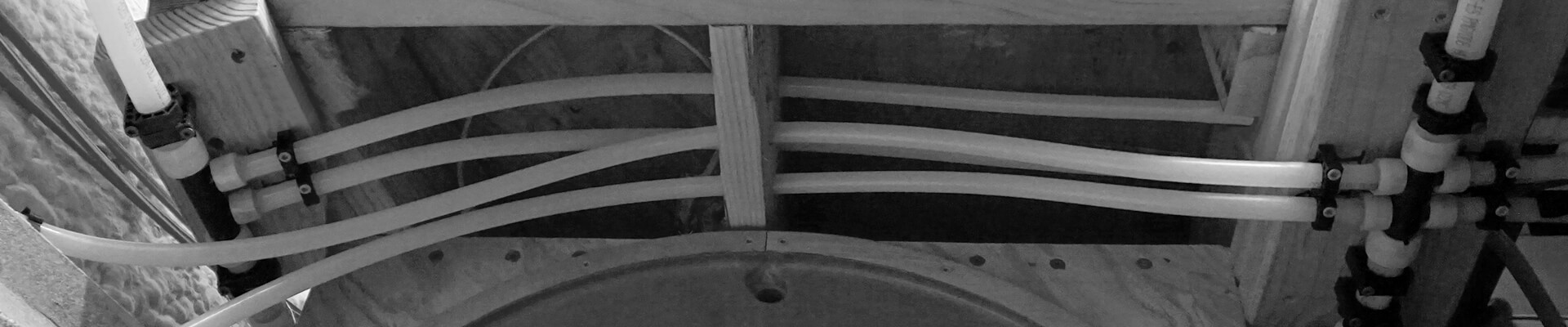
Support the tubing at multiple points to prevent noise from movement or thermal expansion. Use sweeping curves for better flow and to avoid kinks.
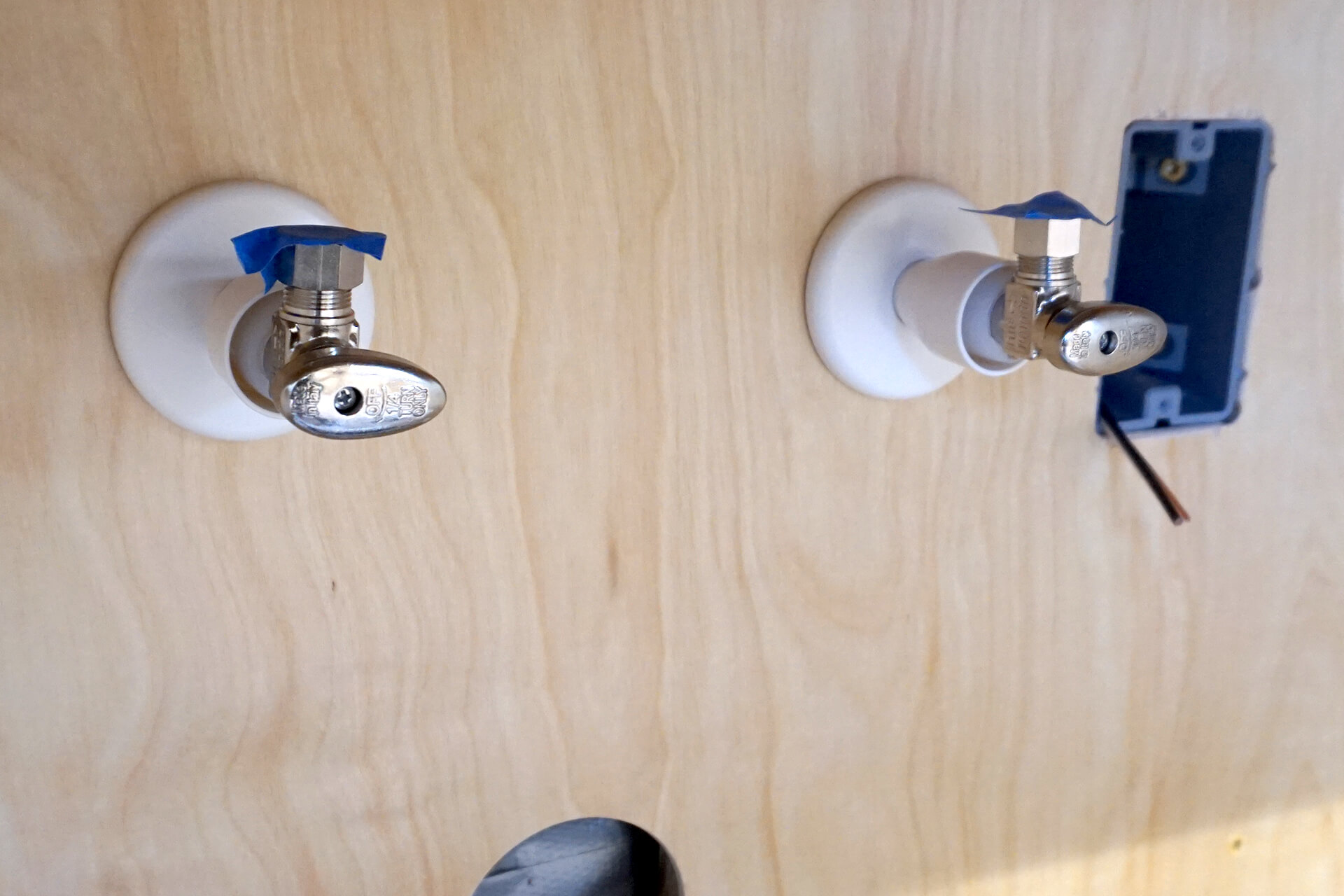
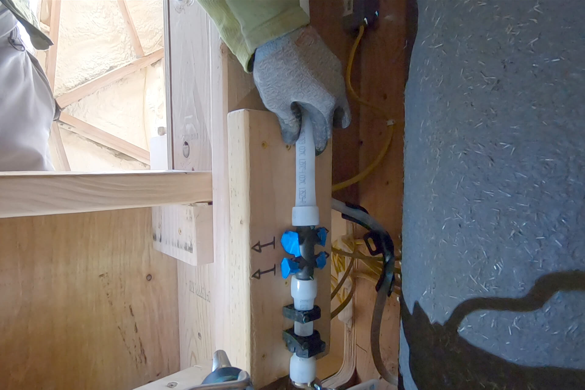
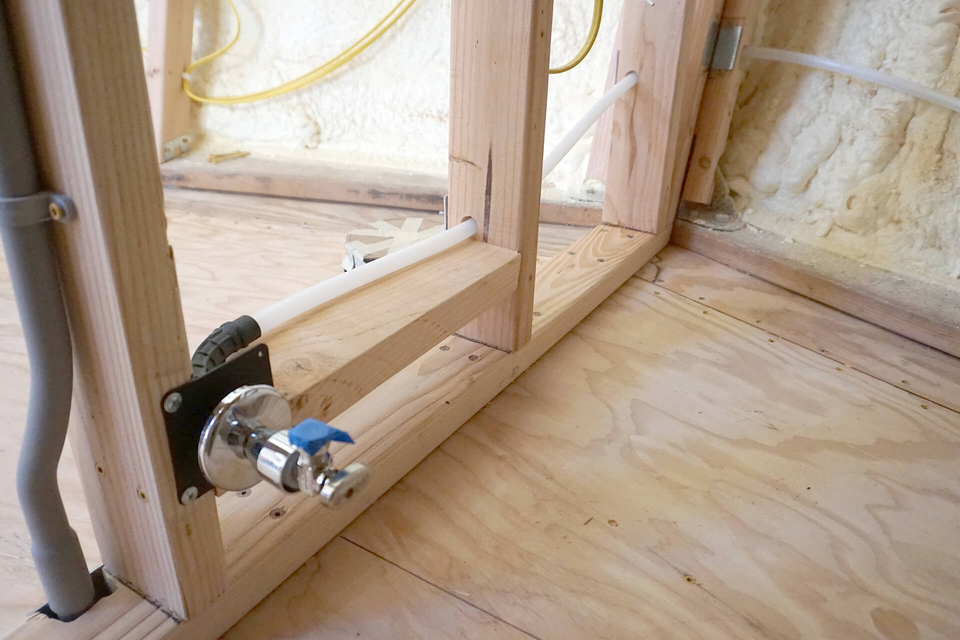
Plumb and install the under-sink stop valves. Hot on the left, cold on the right (as viewed in this photo). Ensure the trim and flared sleeve are slipped onto the tube for a clean finish.
Detail shot of the under-sink stop valve plumbing. Use bend supports to direct the tubing, keeping all home-run plumbing free of fittings between the manifold and the fixtures.
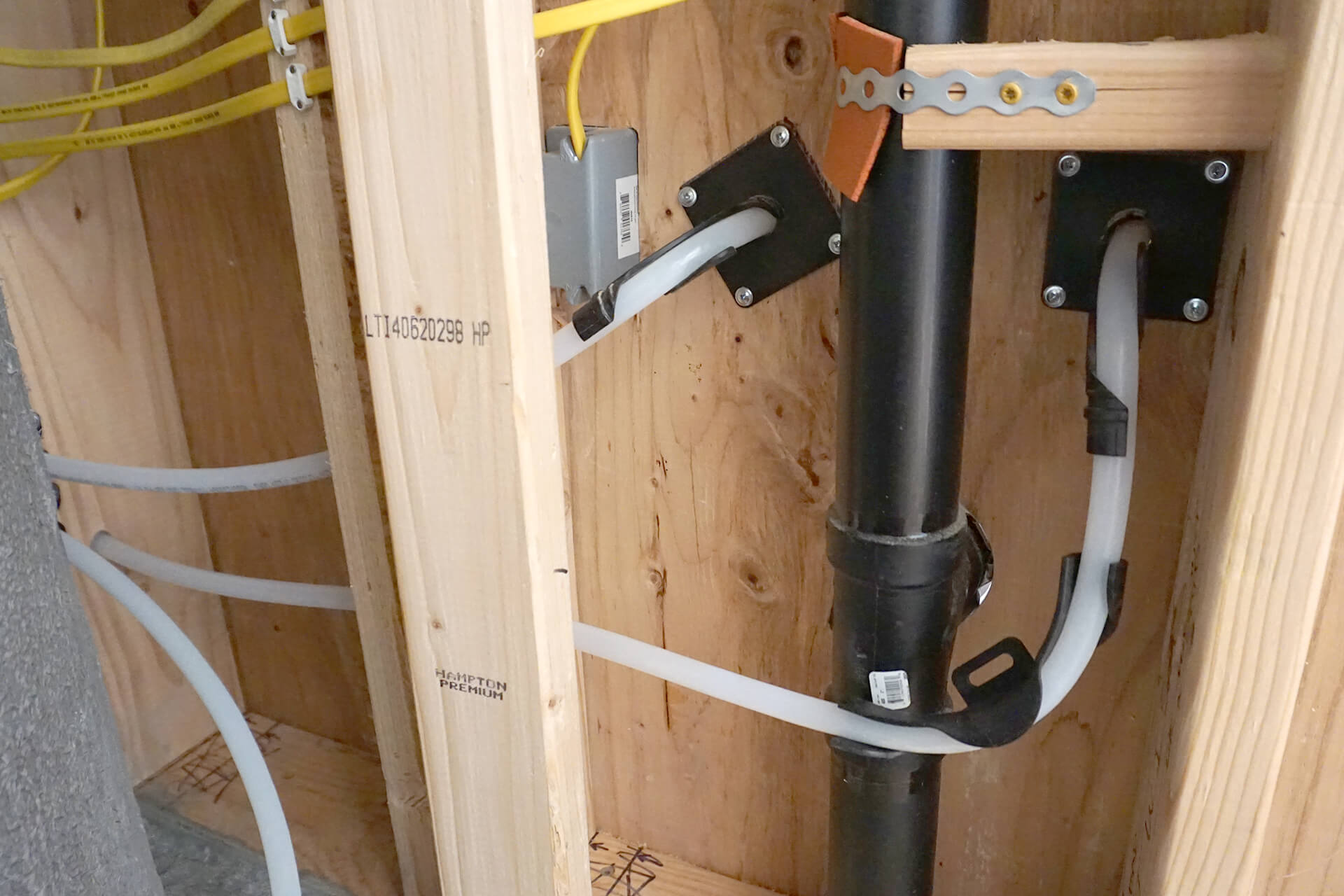
Plumb and install the toilet stop valve in a similar fashion. Install blocking between the wall studs to support the plastic bend support.
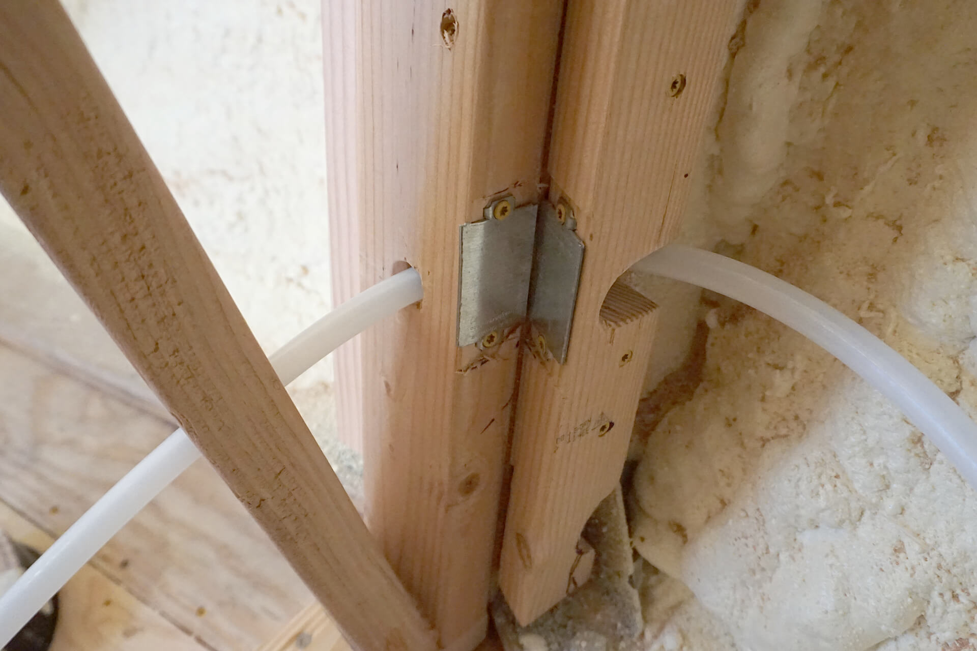
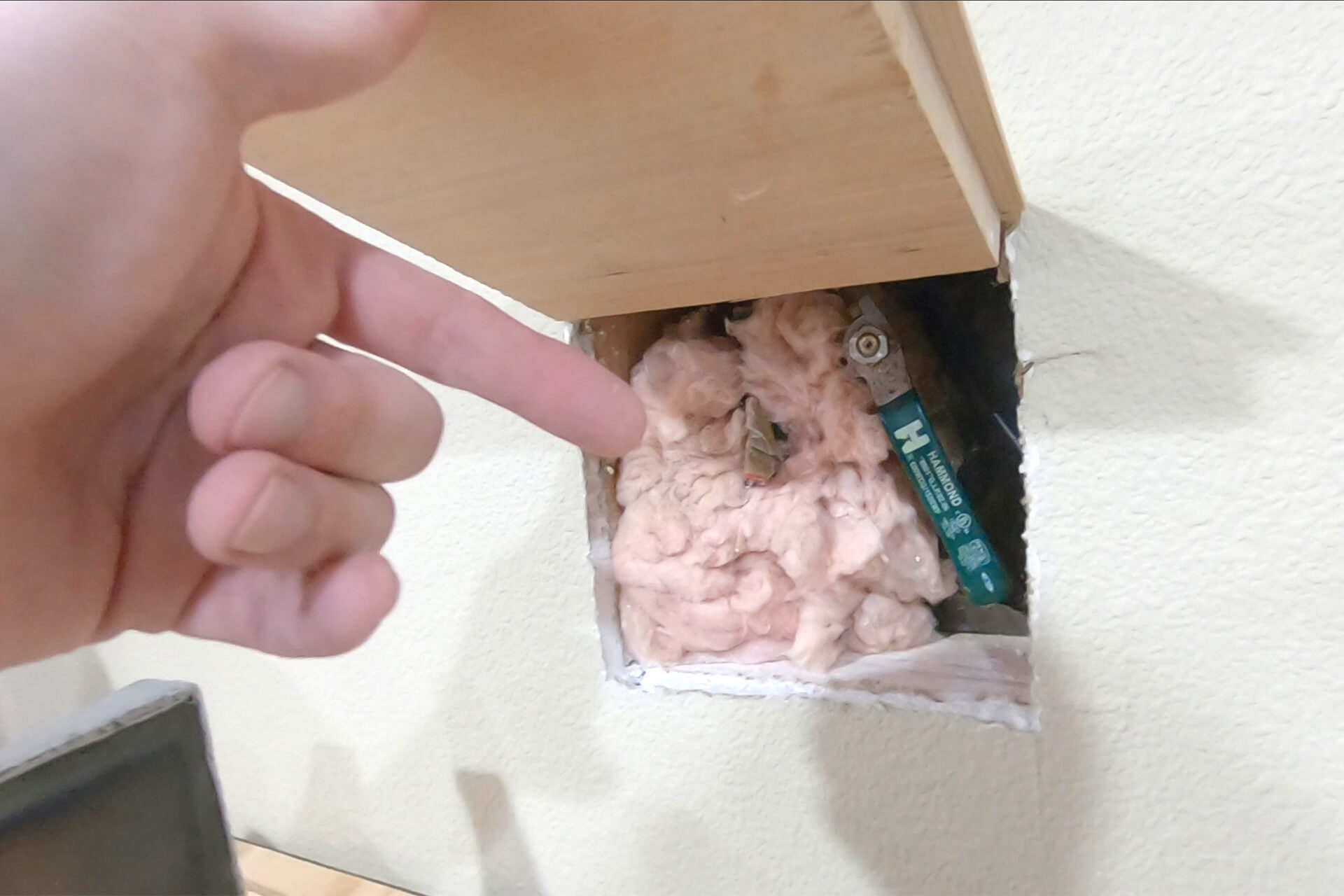
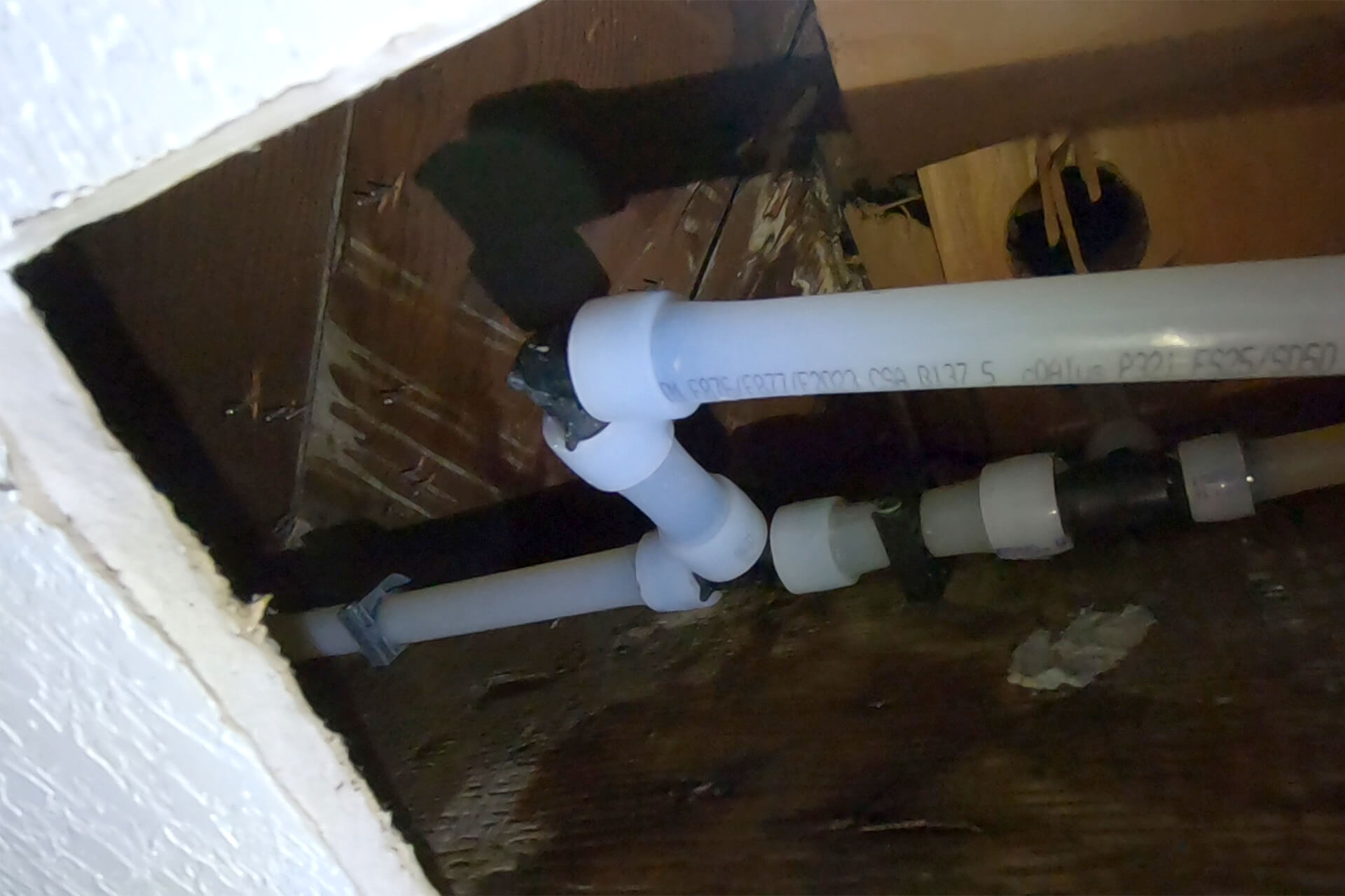
Create and install blocking on either side of the bathroom wall to provide a surface for securing the wall coverings. Install nail protection where necessary to protect the plumbing.
Detail shot showing the continued path of the toilet plumbing.
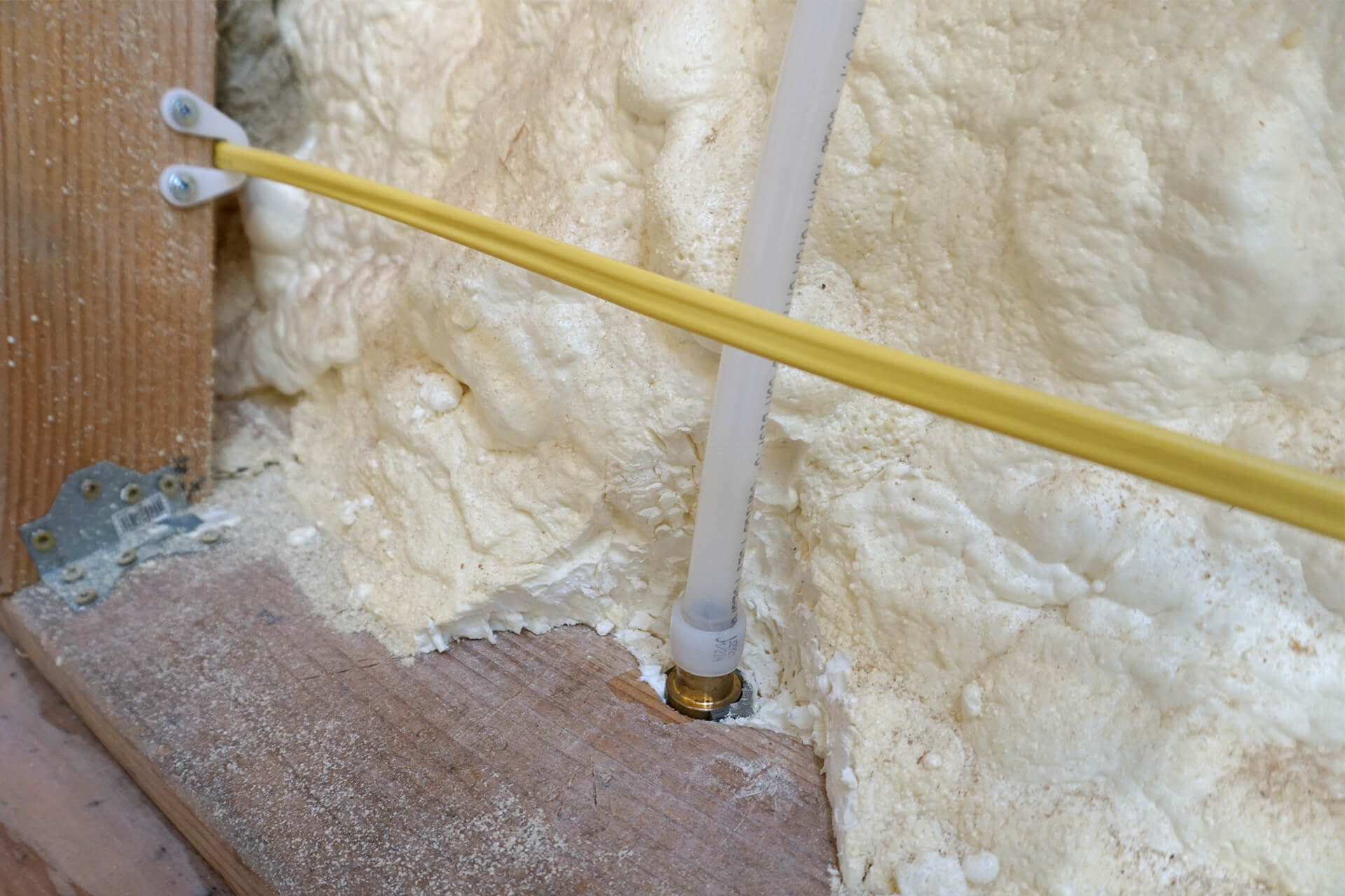
Plumb the hose bib. In hindsight, a dual (hot and cold) hose bib would have been ideal and would have eliminated the need for the mixing valve.
Detail shot showing the path of the hose bib plumbing.
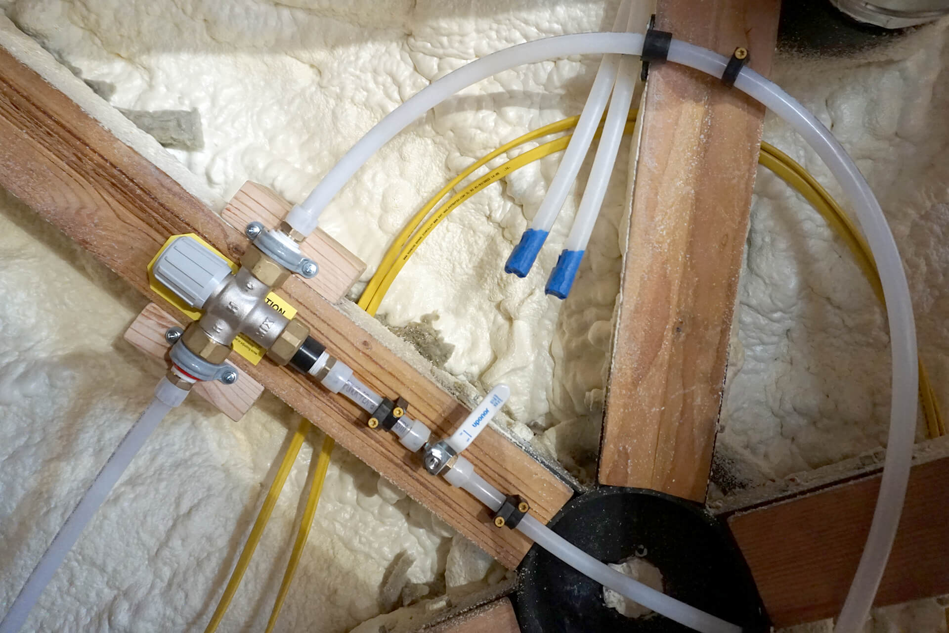
Optional: Install a mixing valve. These are typically used to safely set a water heater above 120°F, but in this case, it is for a warm-water hose bib to act as an outdoor shower.
Optional: Plumb two lines for a sprinkler system and tape the ends. It’s easy to do now while the walls are exposed and will be beneficial if it becomes a requirement in the future.

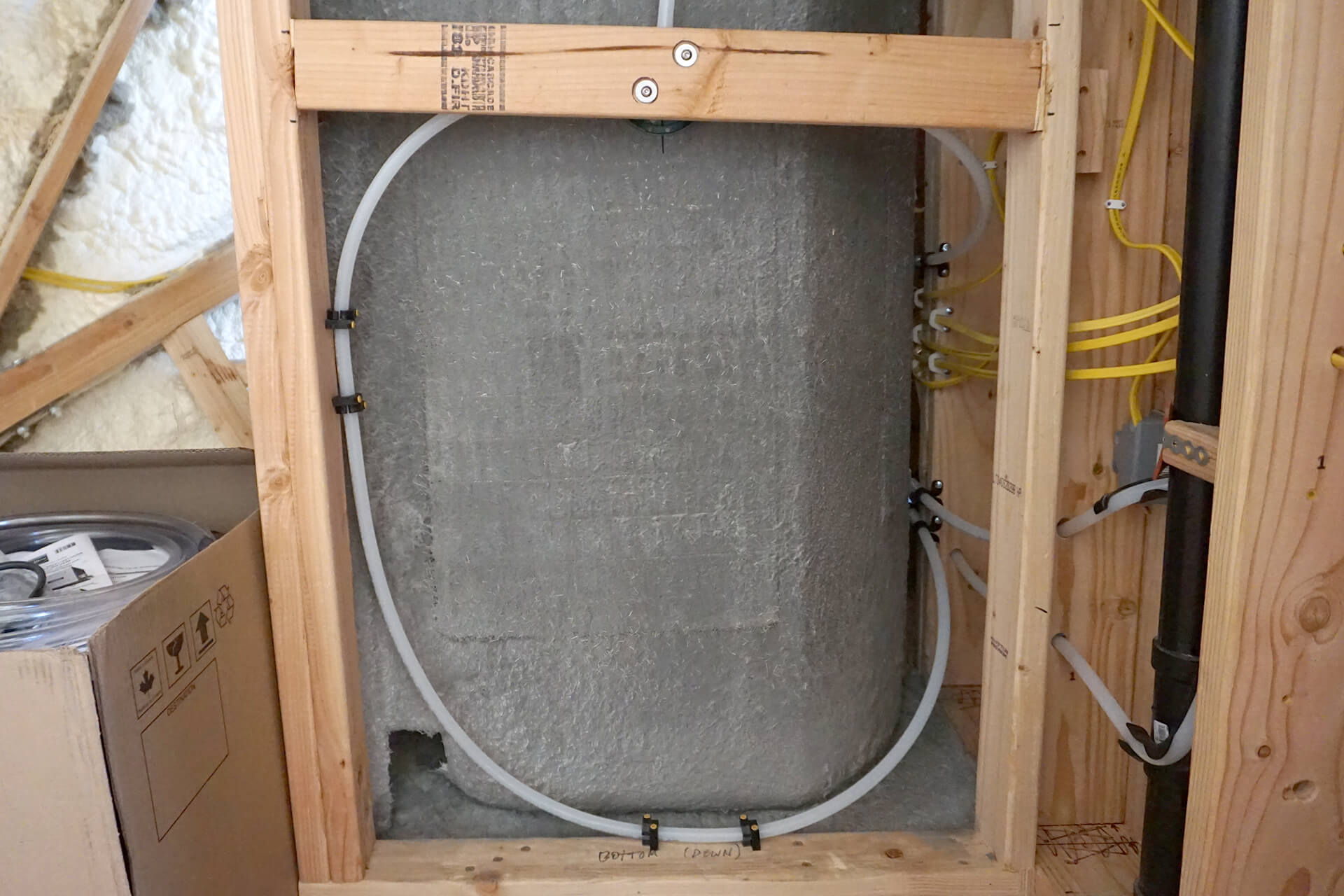
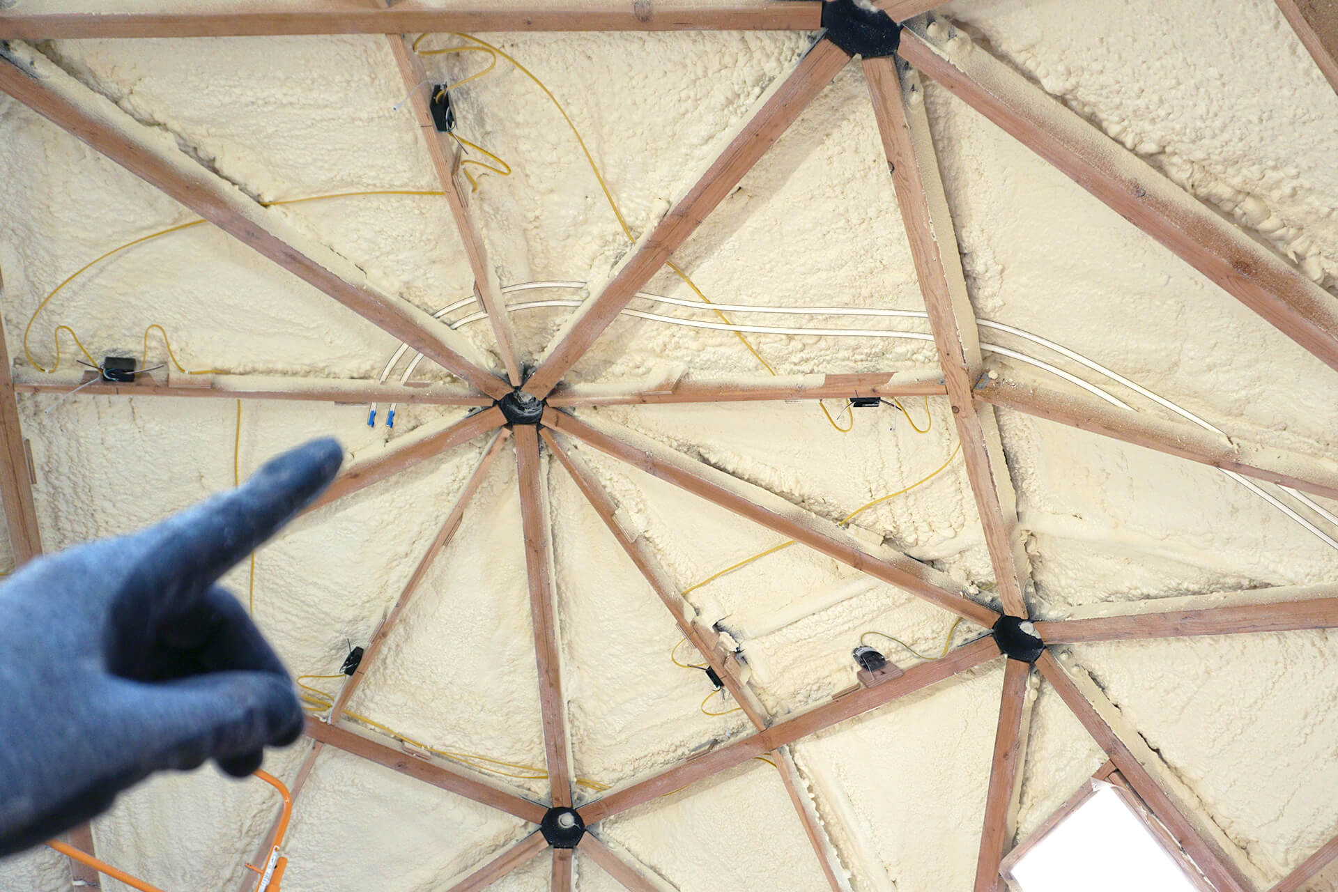
Keep the hot water tank zone clear of tubing by running it through the center wall stud.
The cold water manifold ports (top-down, left-right) are connected to the water heater, hose bib, sink, toilet, shower, and the main water supply (from the primary structure).
The hot water manifold ports (top-down) are connected to the water heater, sink, shower, and hose bib.
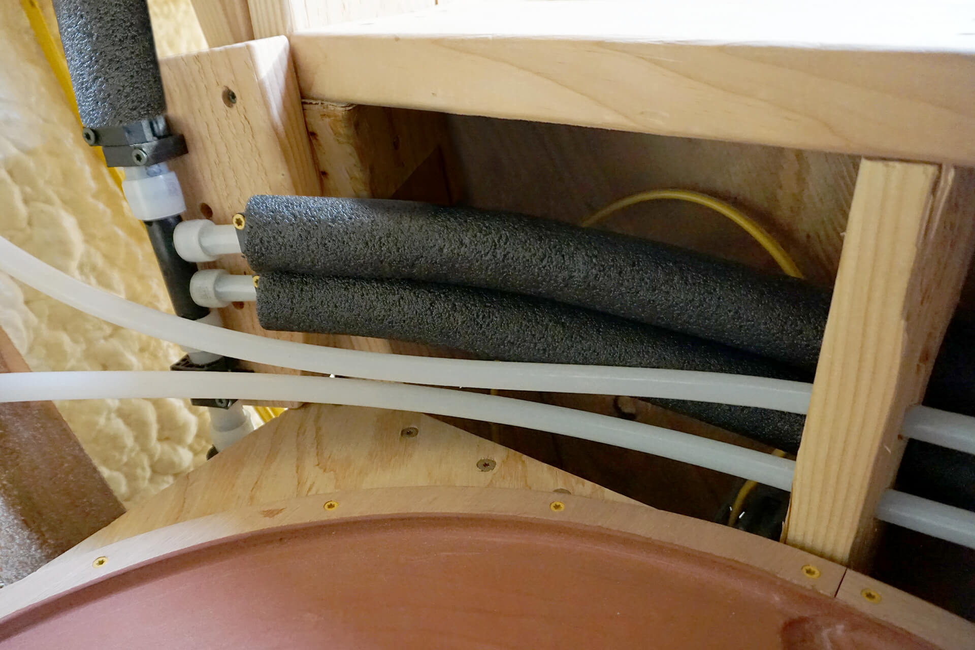
Insulate all hot water tubing to improve efficiency, enhance comfort, and meet code requirements.
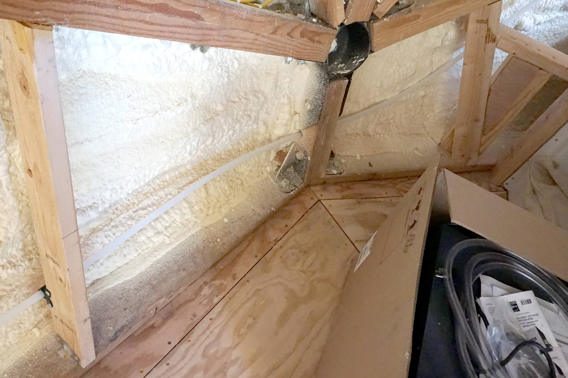
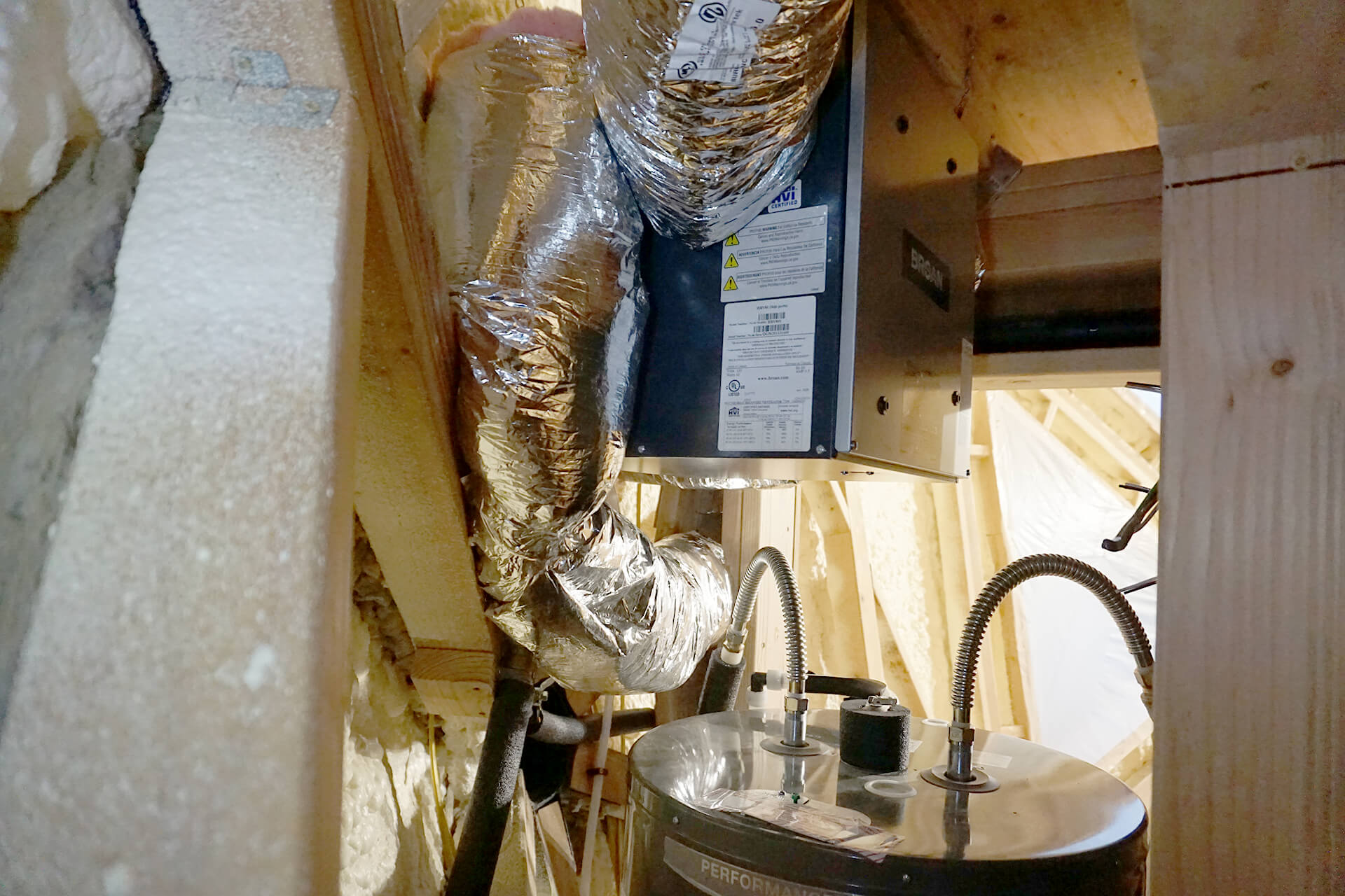
Install rigid duct elbows at the HRV unit wherever tight turns are needed. Flexible ducting can restrict airflow and may collapse when making sharp bends.
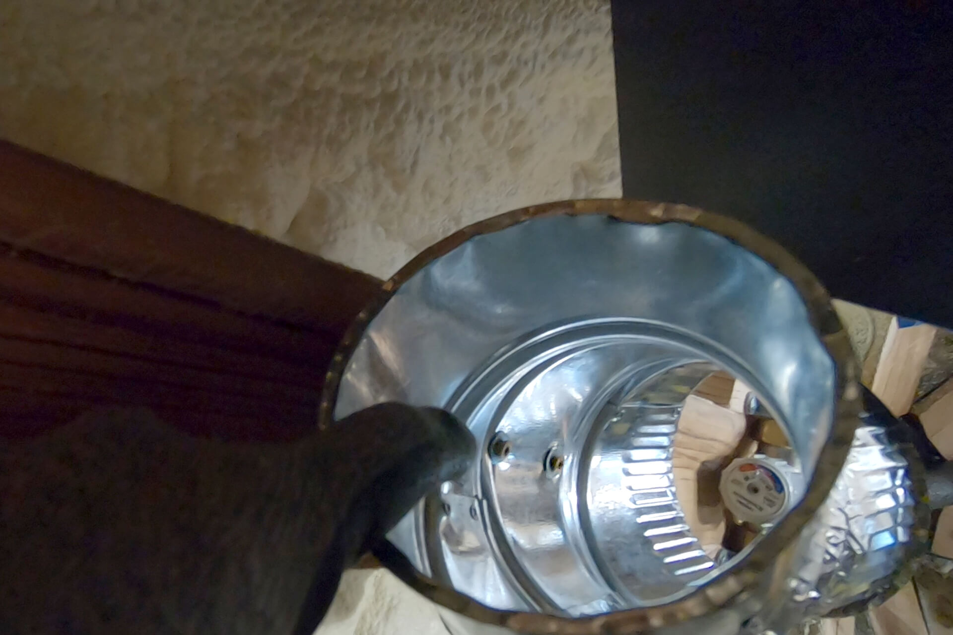
This rigid duct elbow is secured to a wall strut using screws and washers. Flare the end of the elbow to facilitate the attachment of flexible ducting.
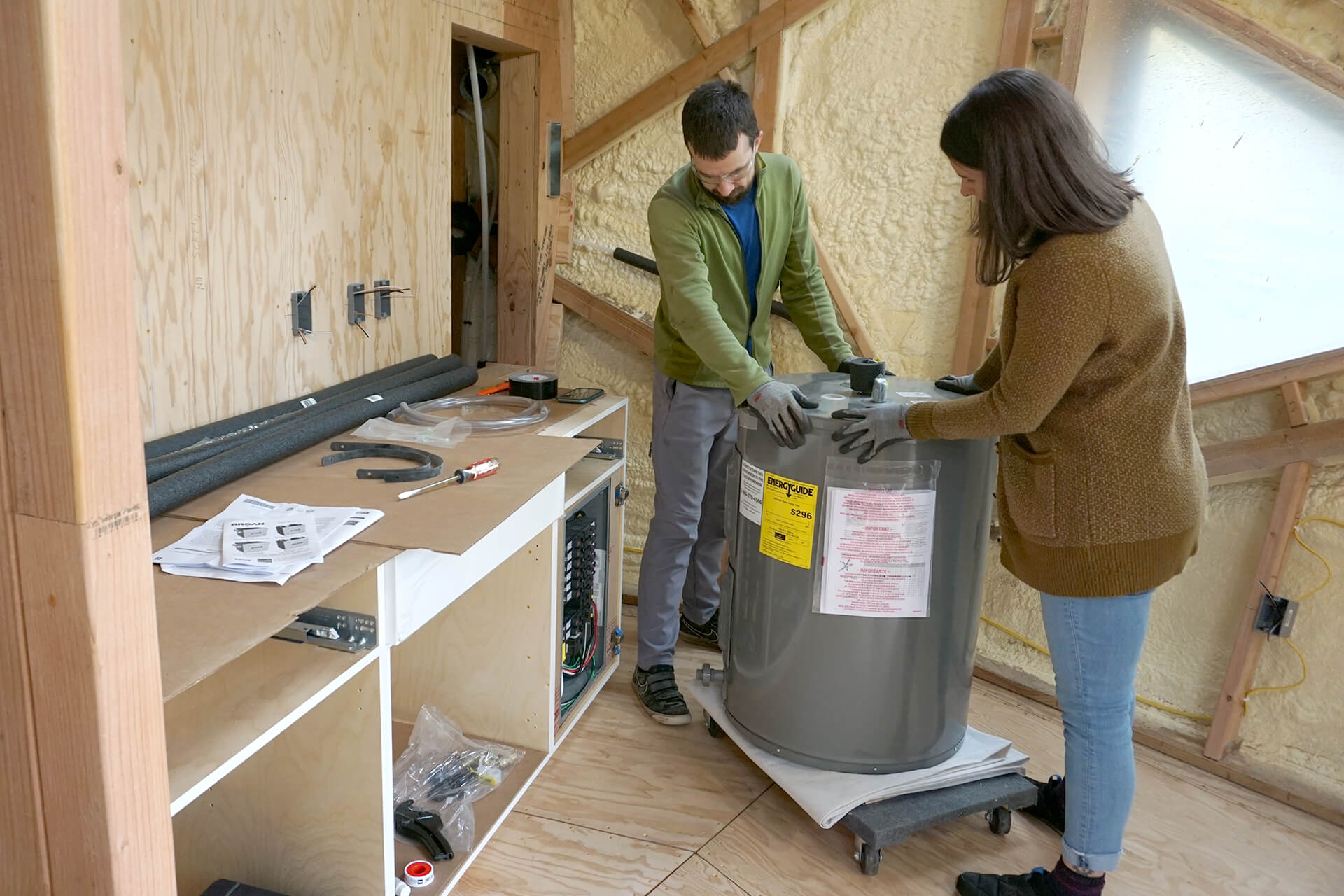
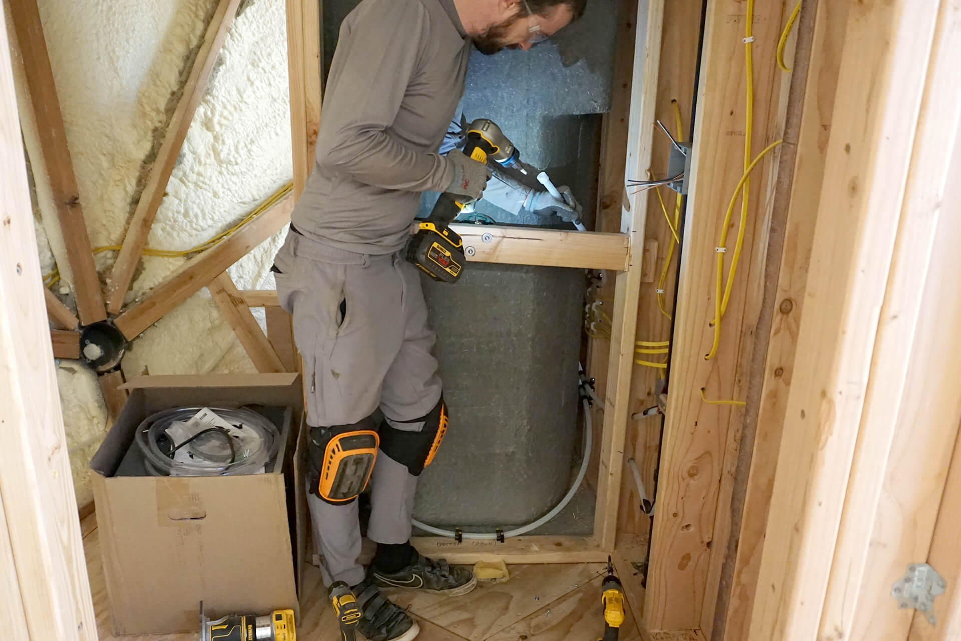
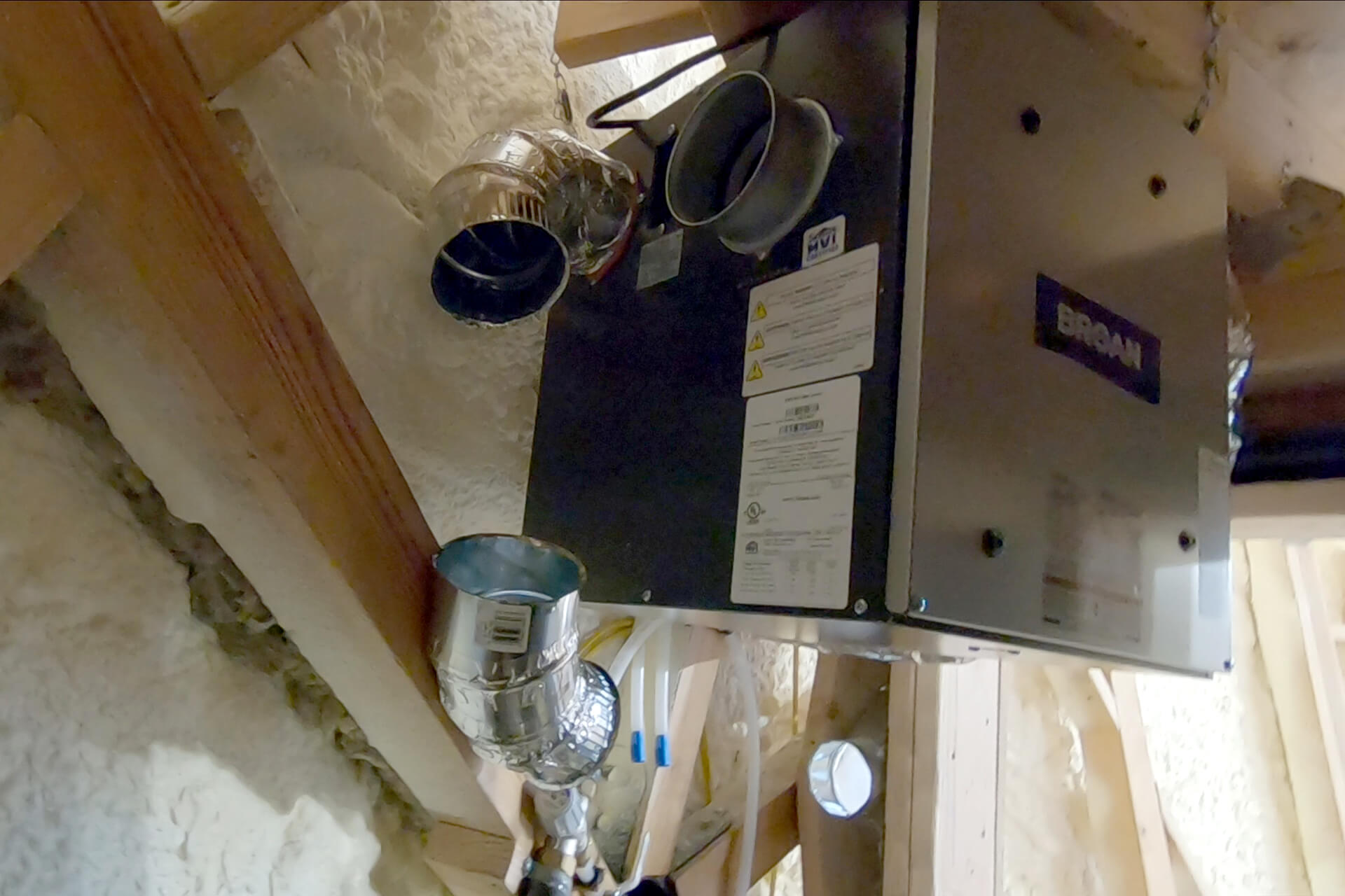
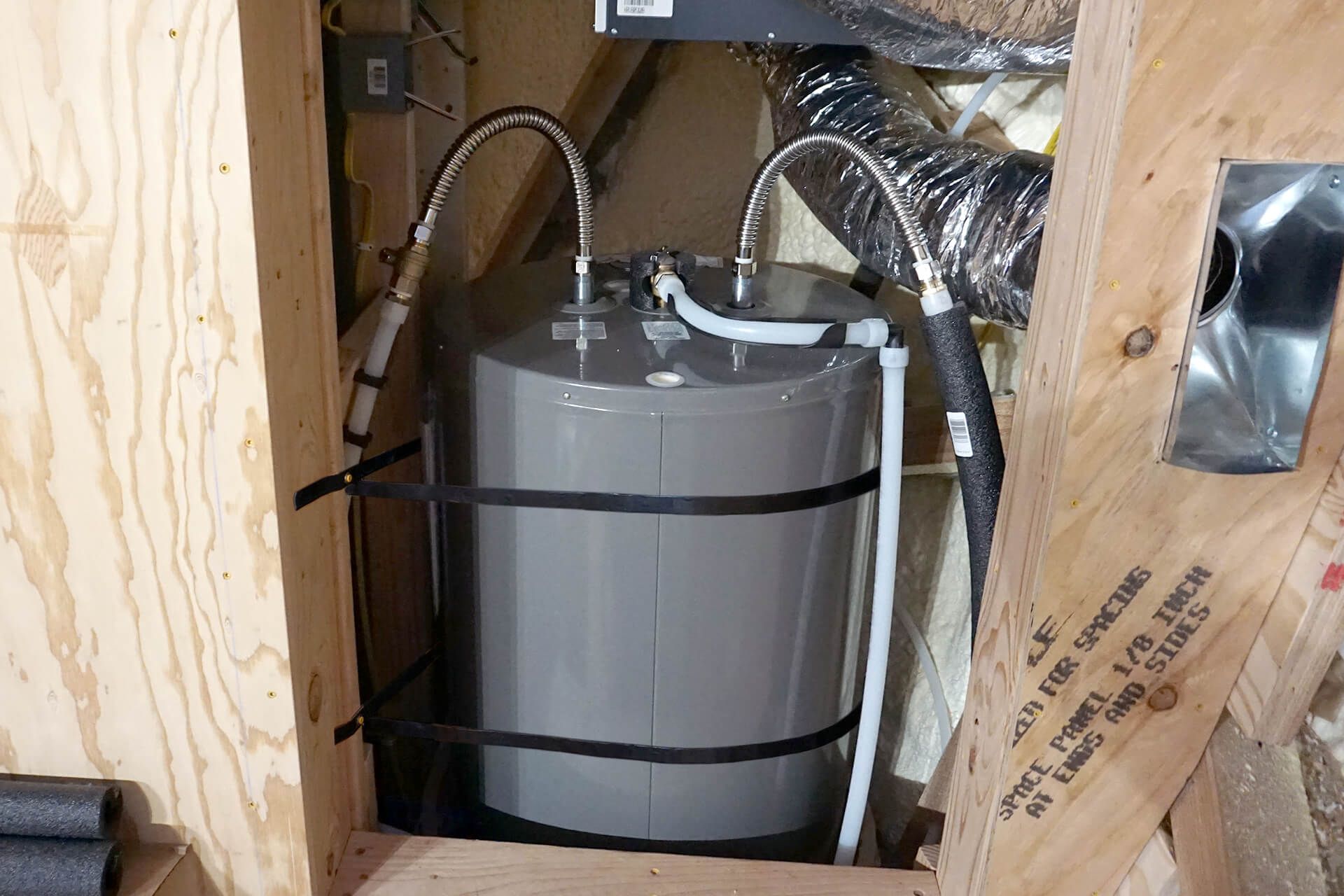
Install the water heater. A 38-gallon "short" unit is shown here, which measures approximately 23" in diameter and 32" in height.
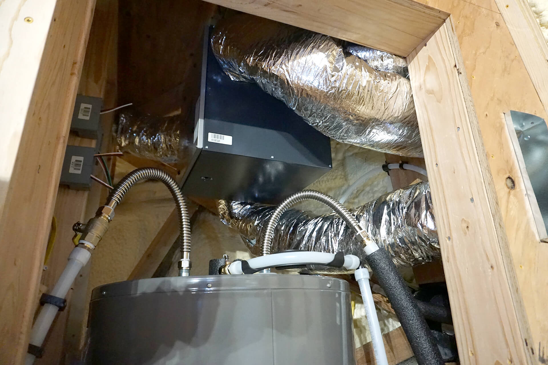
Plumb the water heater and duct the HRV unit. Ensure the cold water supply to the water heater has a shut-off valve and is supported with blocking. Plumb the pressure relief valve downward.
Use corrugated stainless steel water heater connectors for their longevity and efficiency. Plumb them with a heat trap bend as shown to prevent heat loss and improve system efficiency.
If the dome’s water source is from the primary structure, shut off its water supply. Tip: When turning the water supply back on, do so slowly to avoid spiking the pressure and causing leaks.
Splice the larger diameter PEX from the dome into an equivalent or greater diameter water line in the primary structure. Slowly turn the water back on and check for leaks.
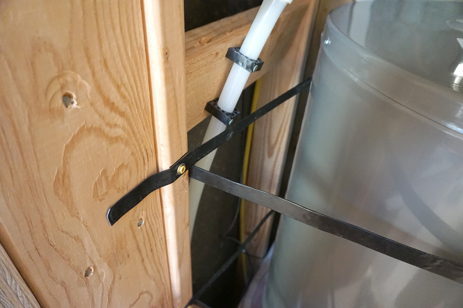
Secure the water heater tank with strapping, placing one strap in the upper third and another in the lower third of the water heater's vertical dimension.
Congratulations on completing the plumbing rough-in! Ensure the whole system is pressurized with no leaks and then call for an inspection.
Inspections: Rough-In/Top Out, Water Heater, Water Service, (and Circuits/Feeders)