Metalwork – Railing
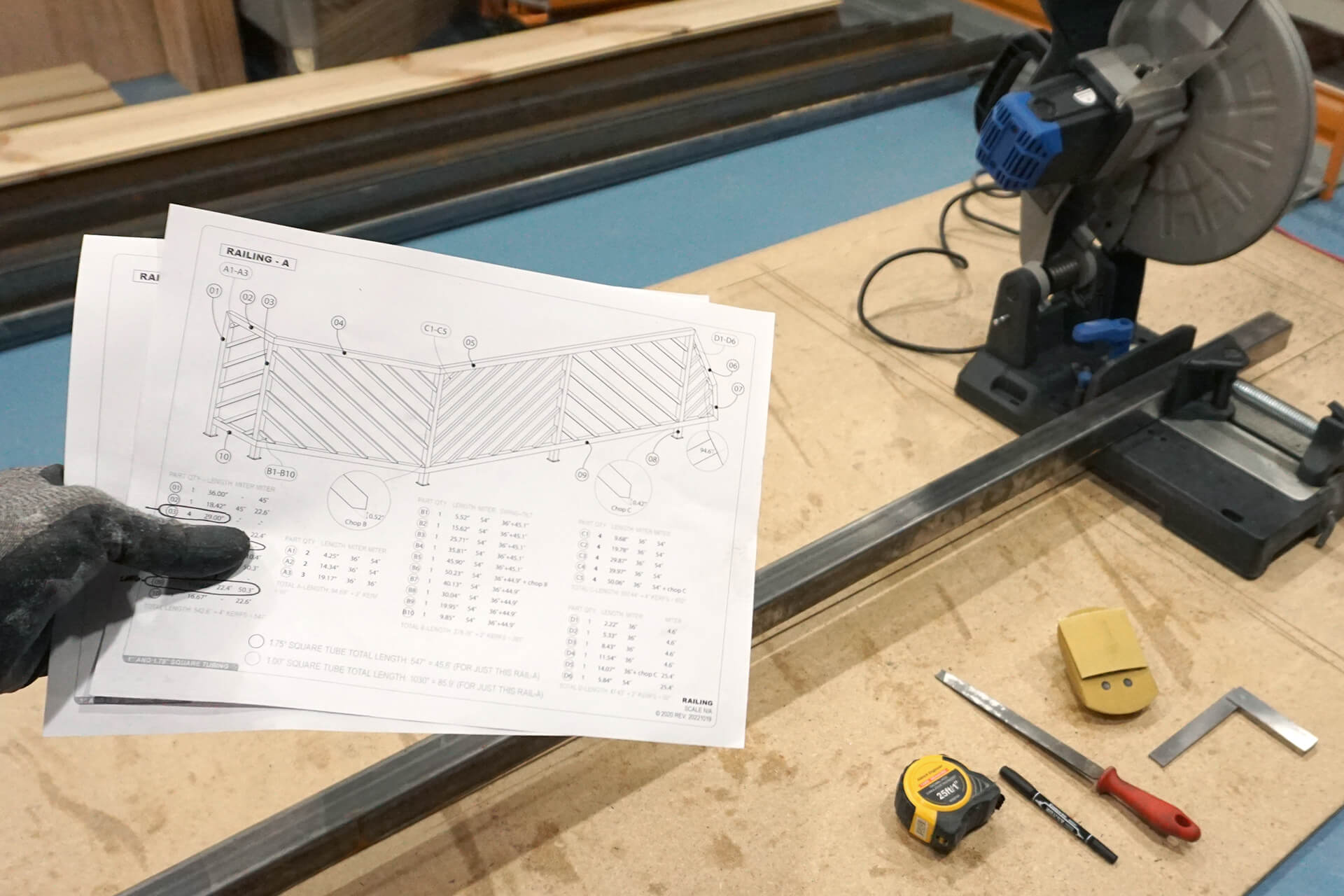
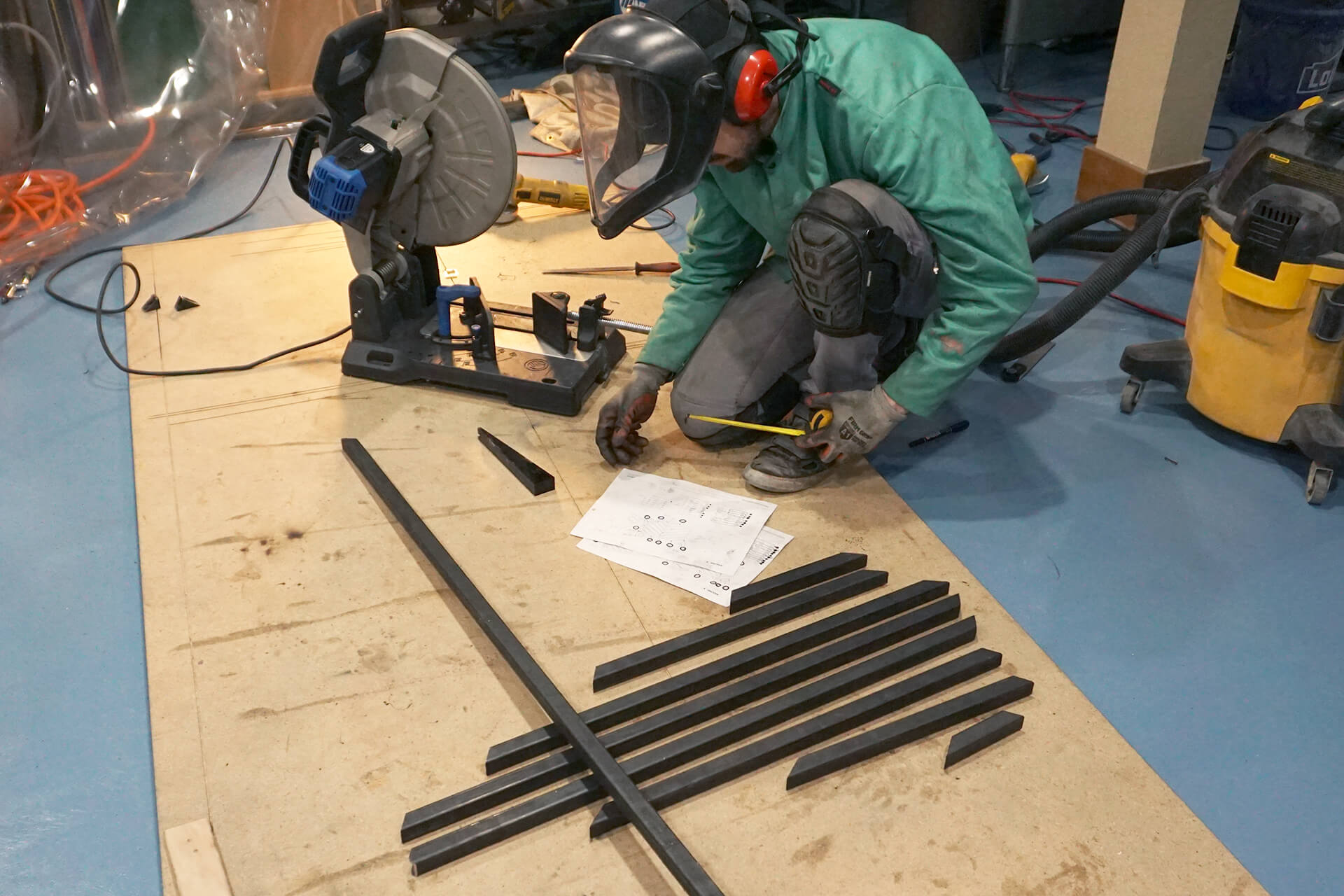
Consult the Railing construction drawings. The length and angle of each piece are specified in the detailed drawings.
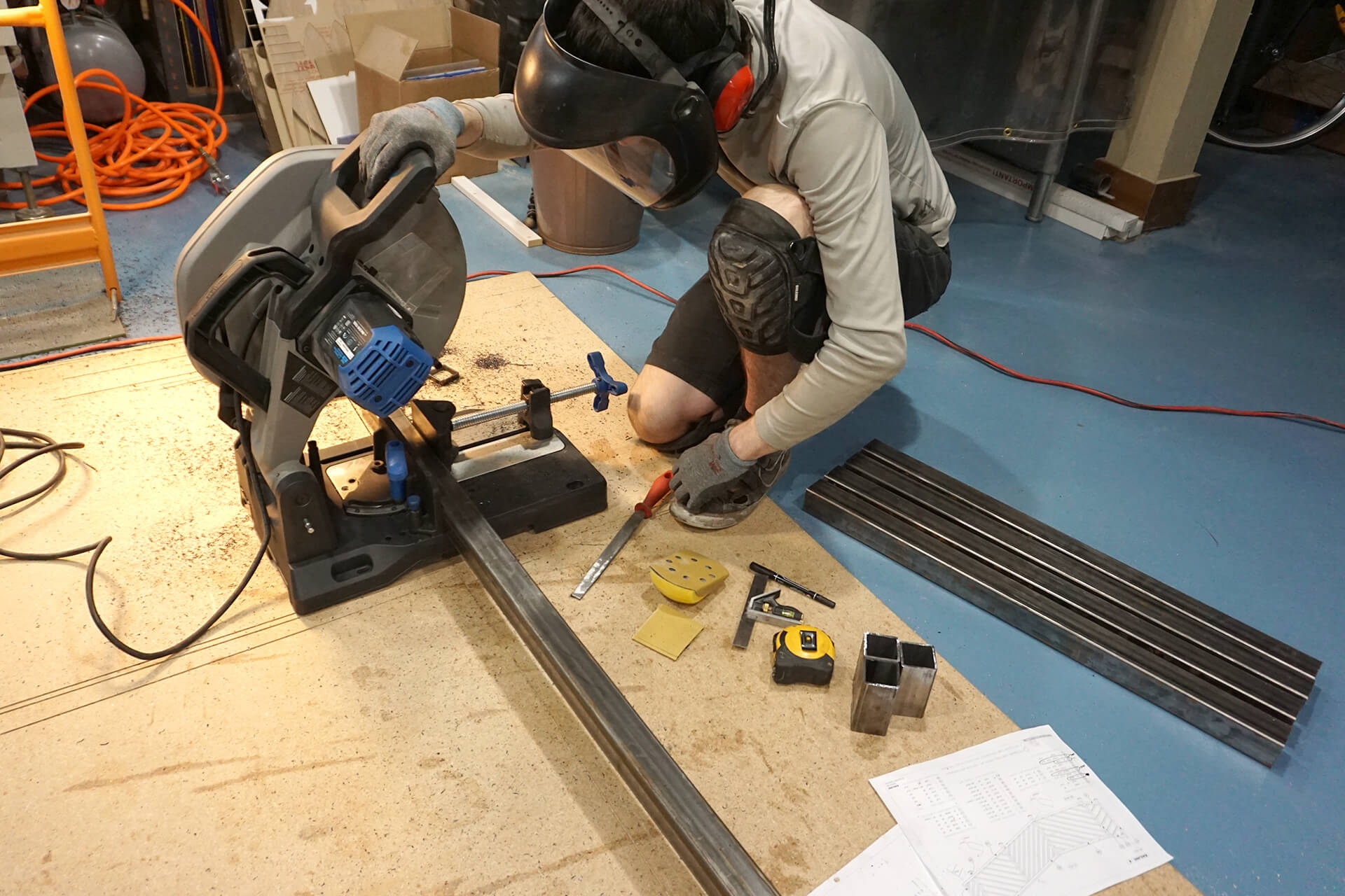
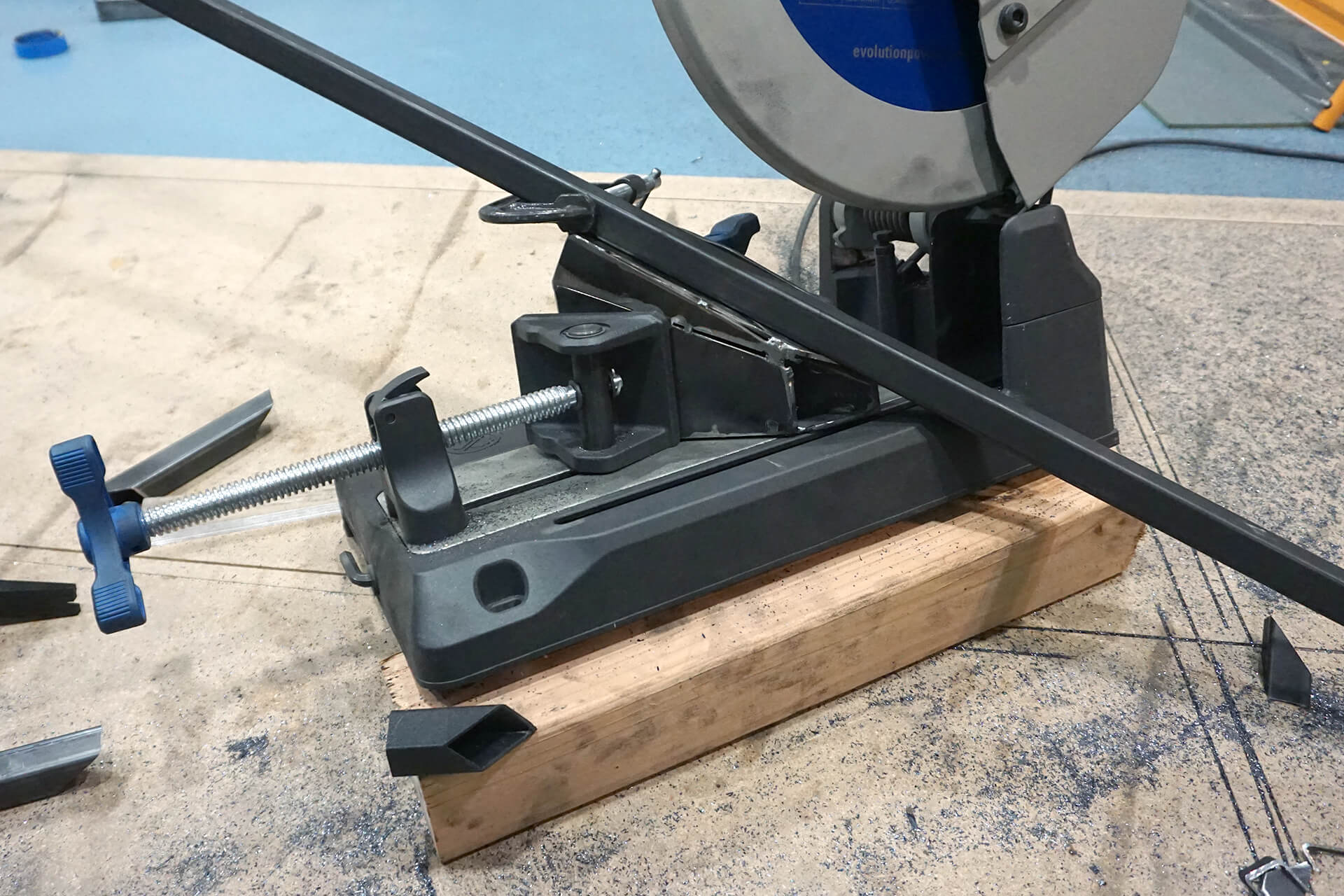
Cut the frame pieces from 1.75” square steel tubing. A metal-cutting chop saw with a 14” blade is shown here. Debur the cut ends with a file.
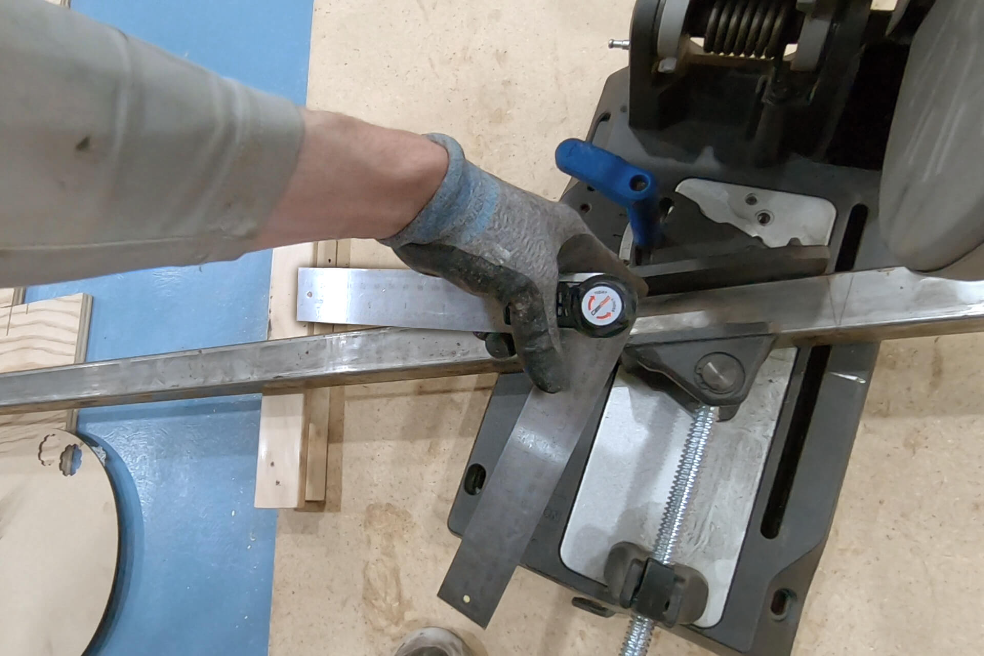
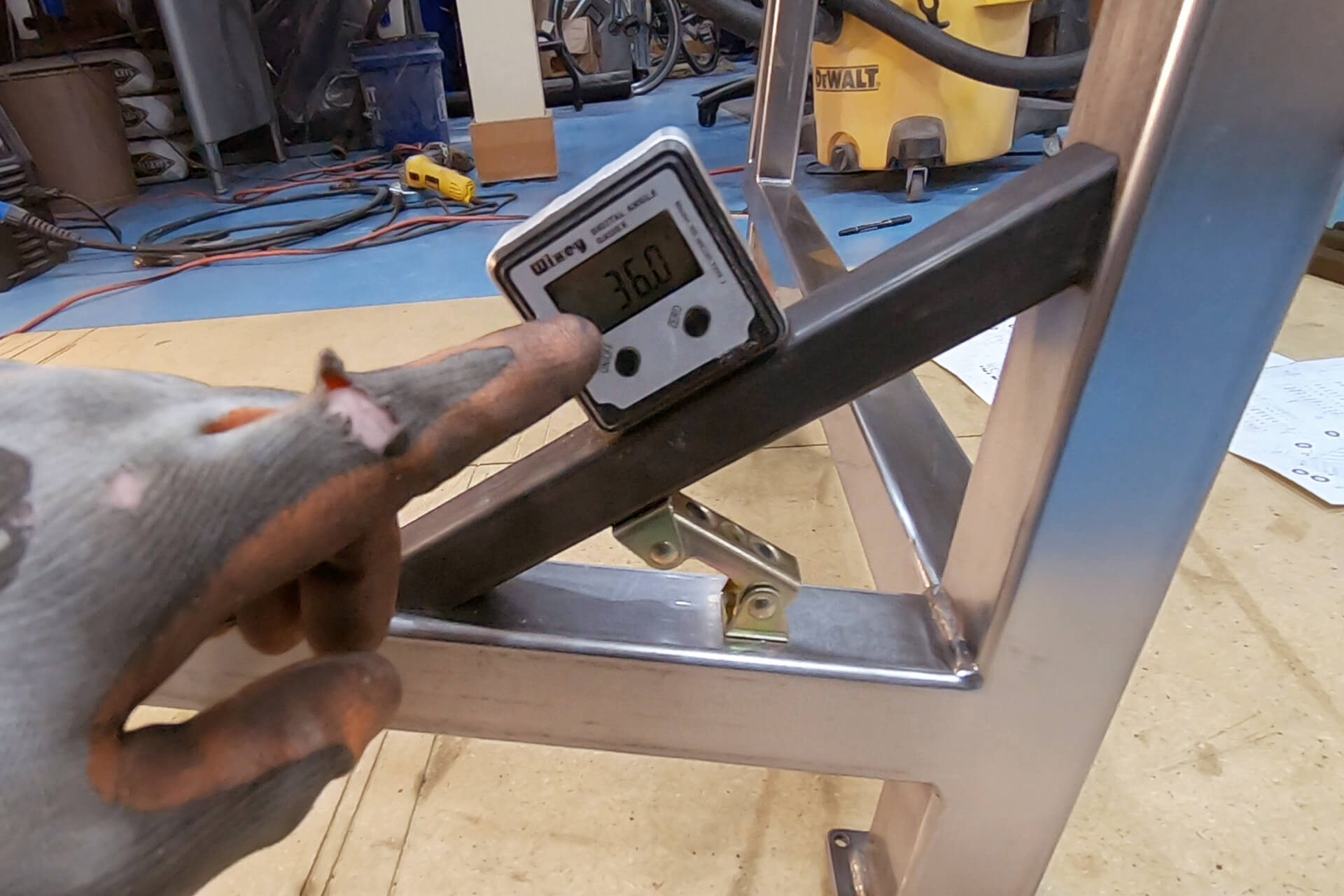
Use a digital angle finder to verify the accuracy of the adjustable fence markings for miter cuts.
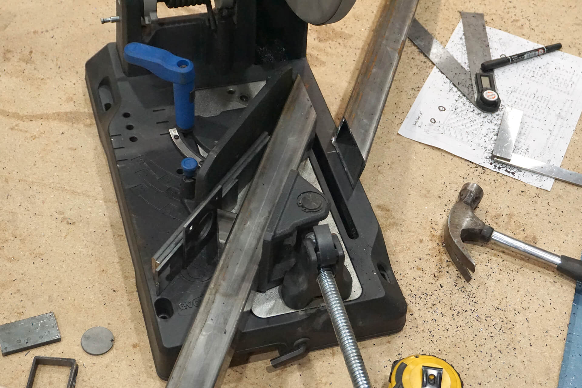
While risky, spacers can be used for miter cuts that exceed the fence’s maximum angle. An effective 58.6-degree fence angle is shown here.
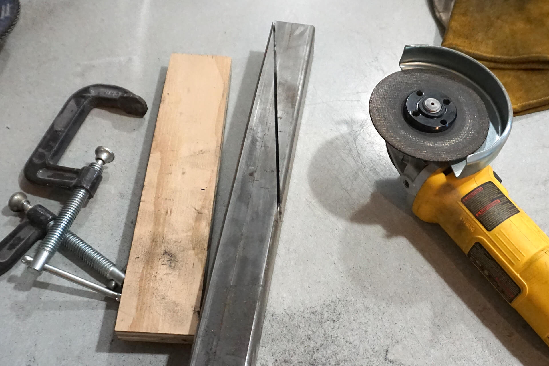
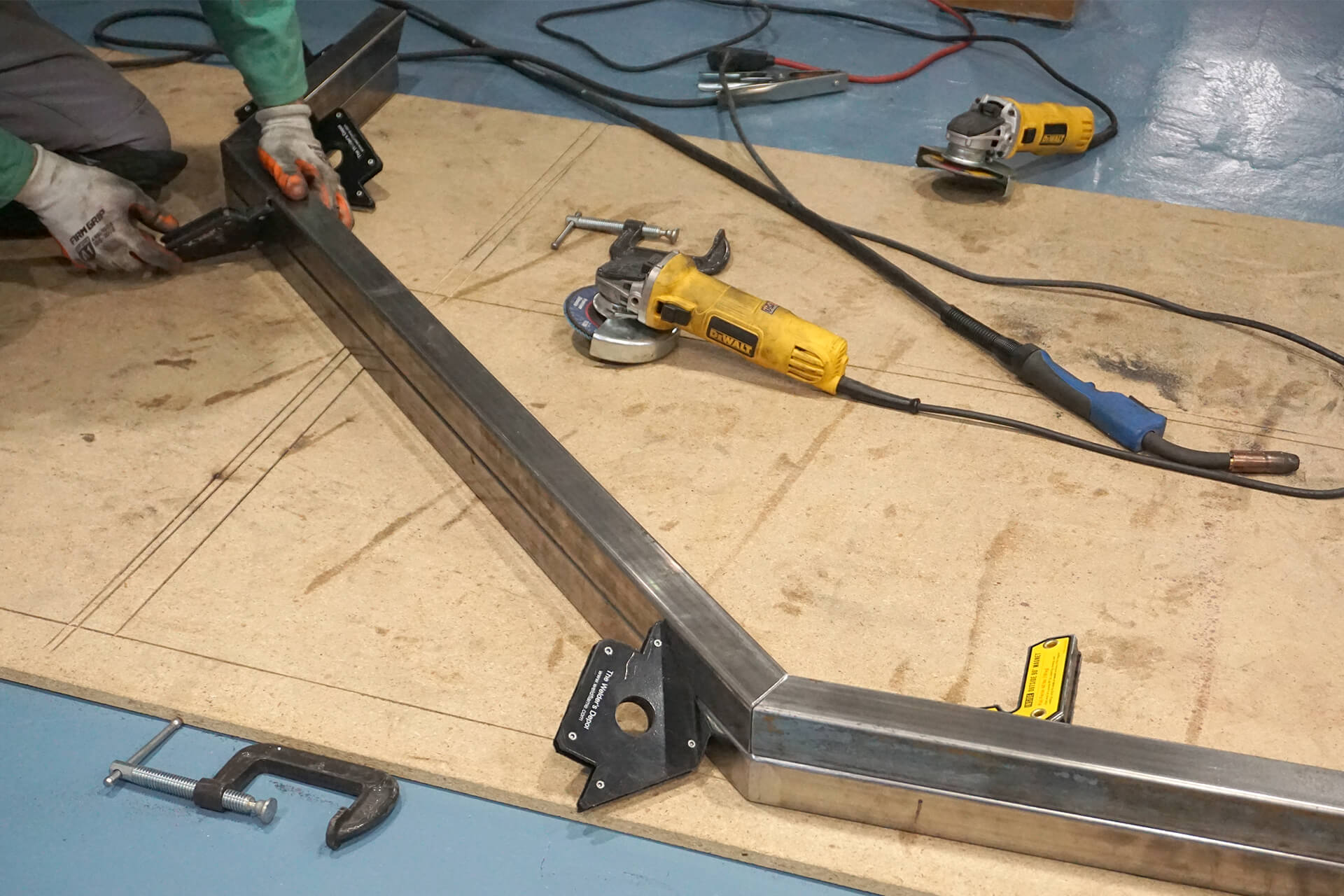
For extreme angles, cut with an angle grinder equipt with a metal cut-off disc. Clamp a sacrificial plywood guide and cut one side at a time.
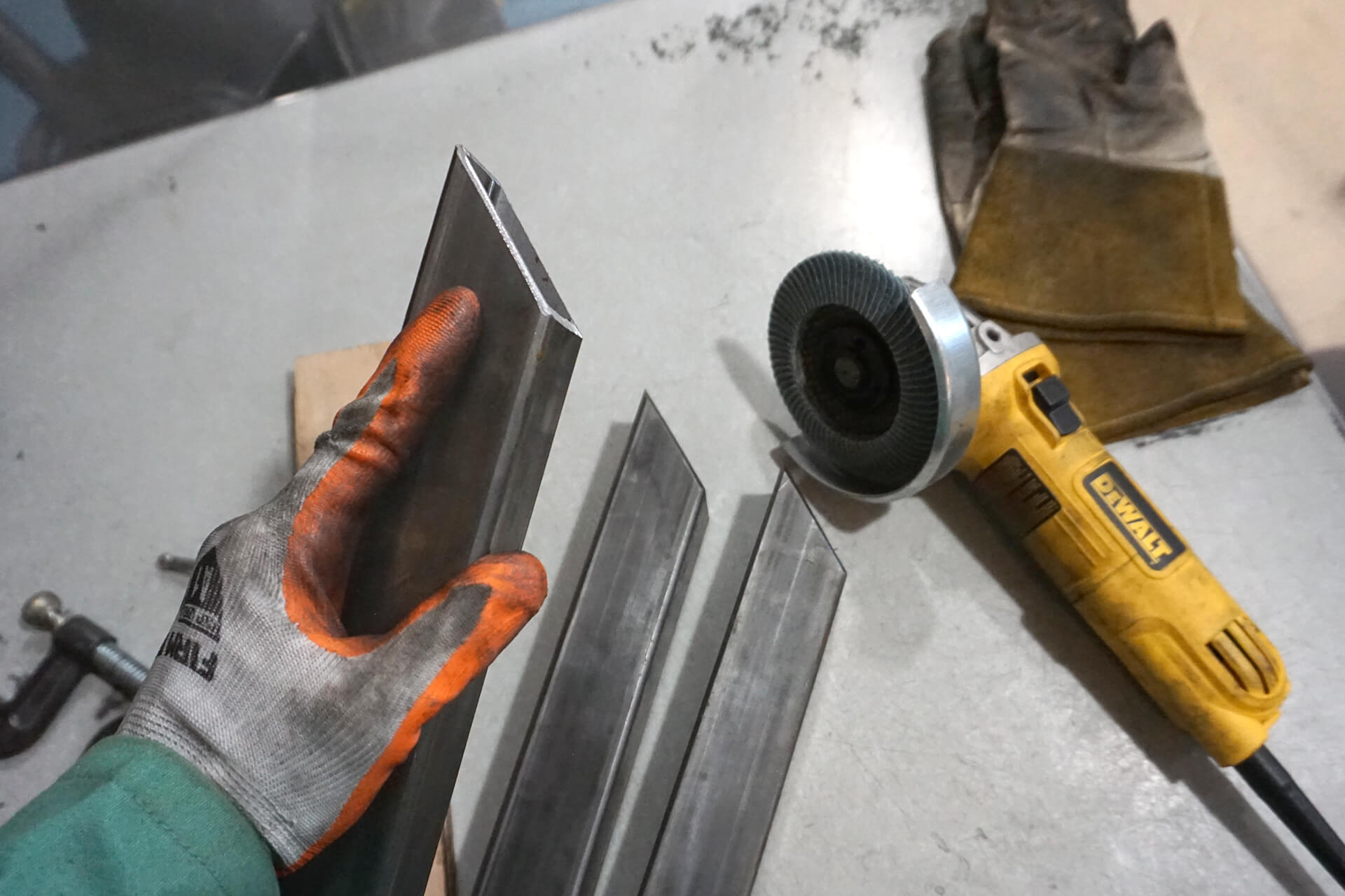
Use an angle grinder with a sanding disc to slightly bevel the angled cuts to ensure full material penetration during welding.
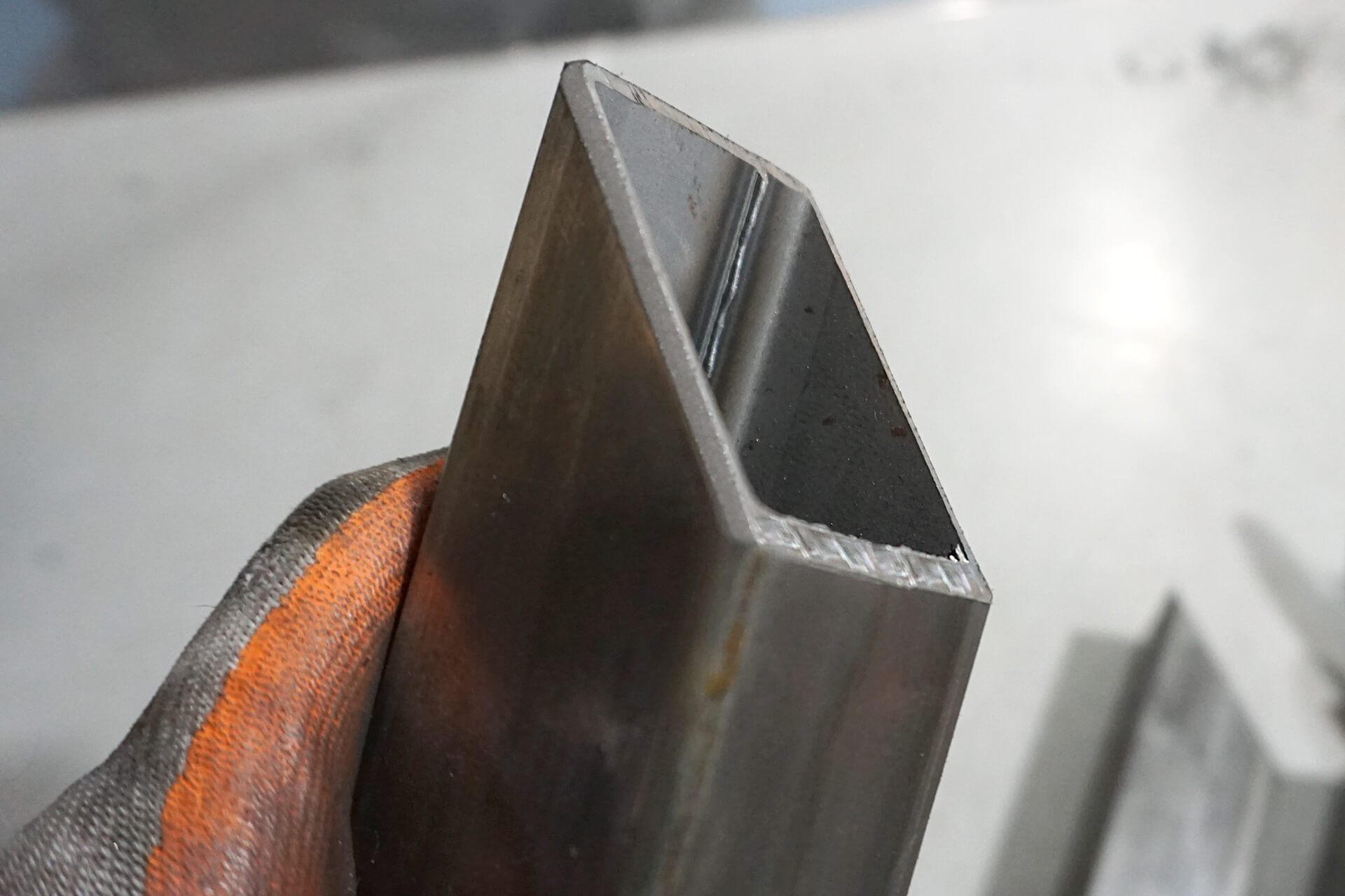
Detail shot showing the beveled edge. Note that a small amount of the original cut surface remains for alignment.
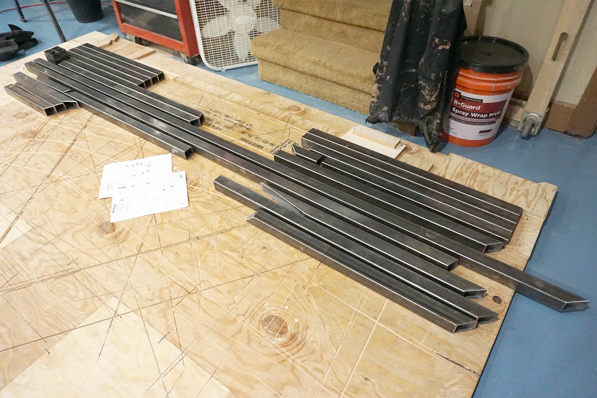
Stack all frame pieces for both railings in preparation for welding.
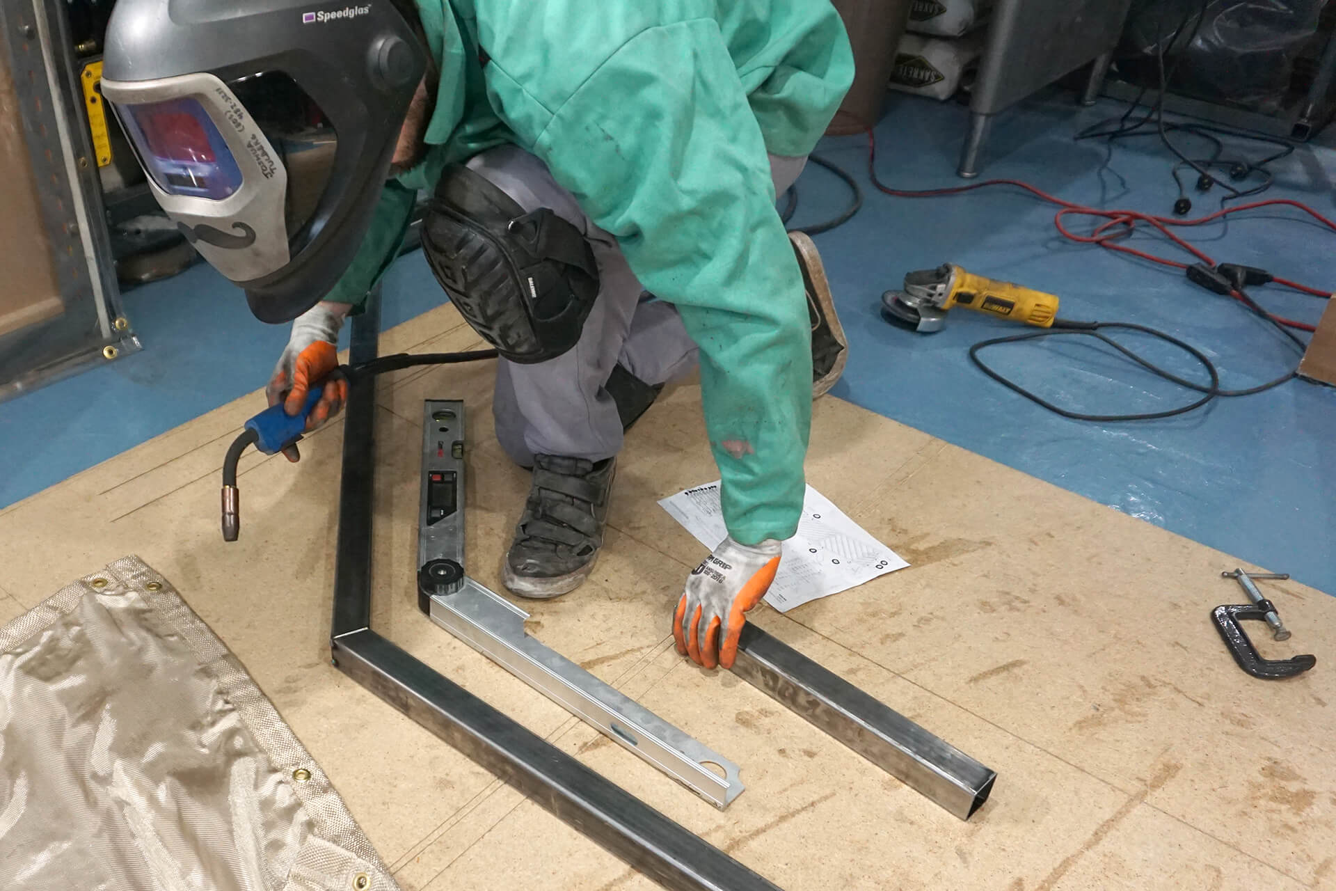
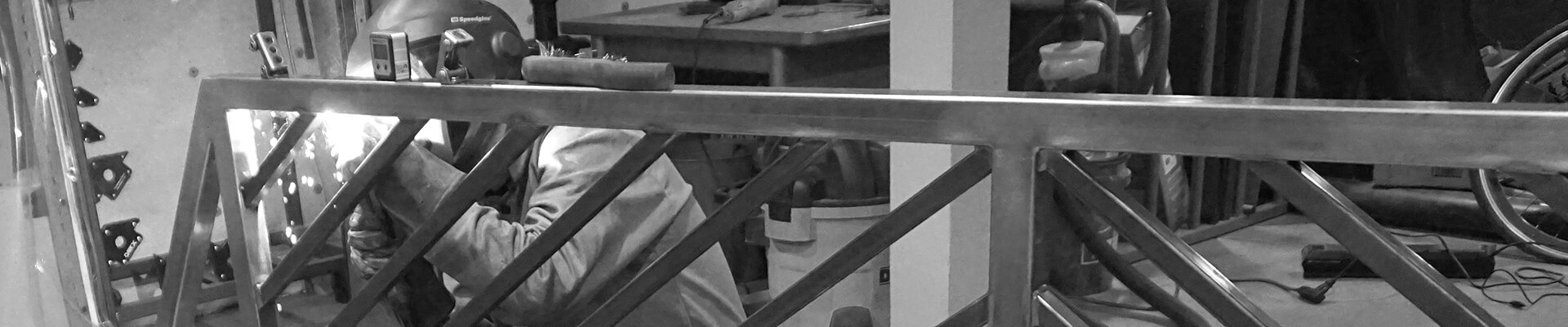
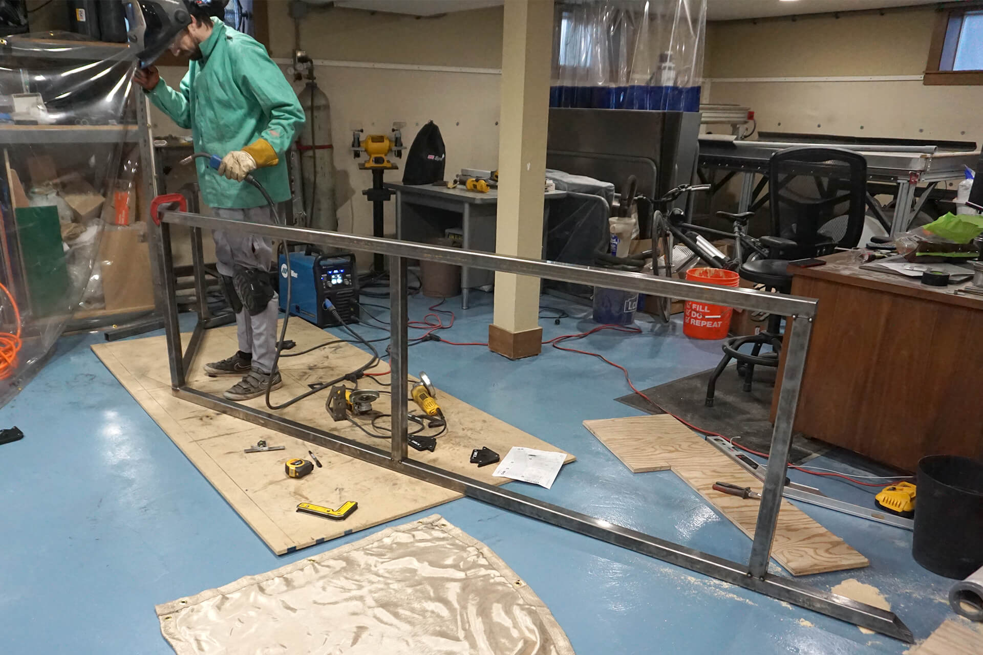
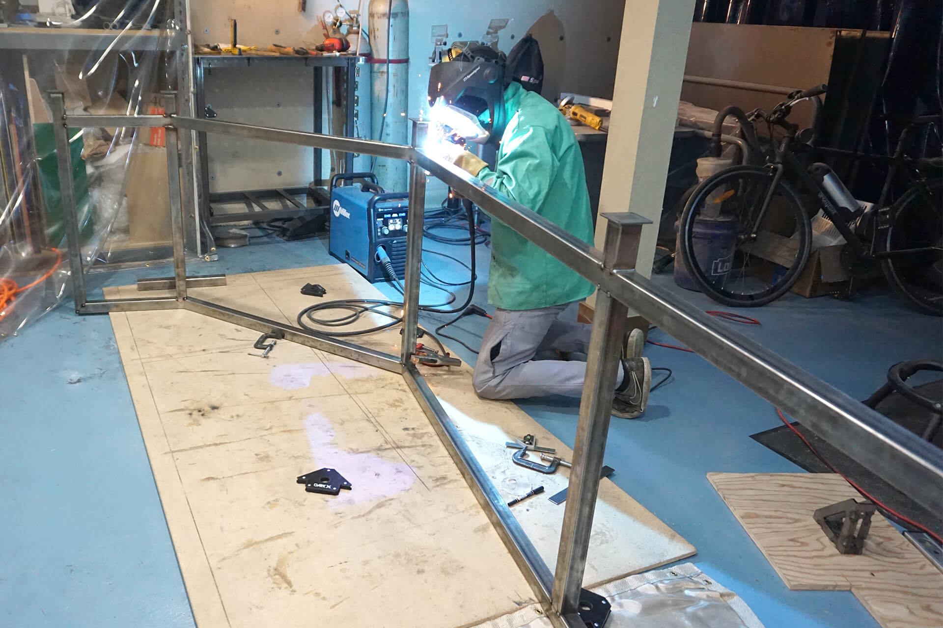
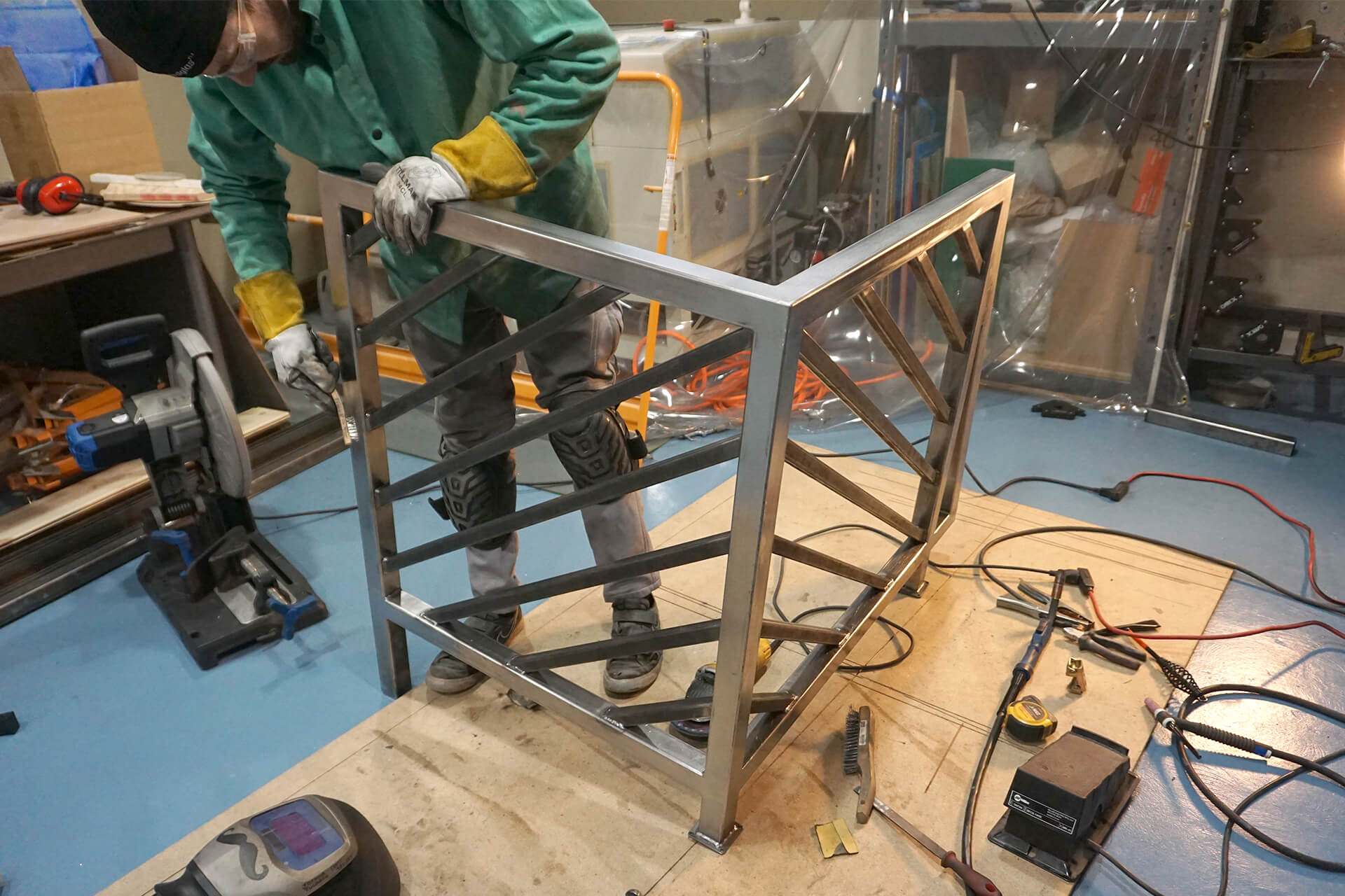
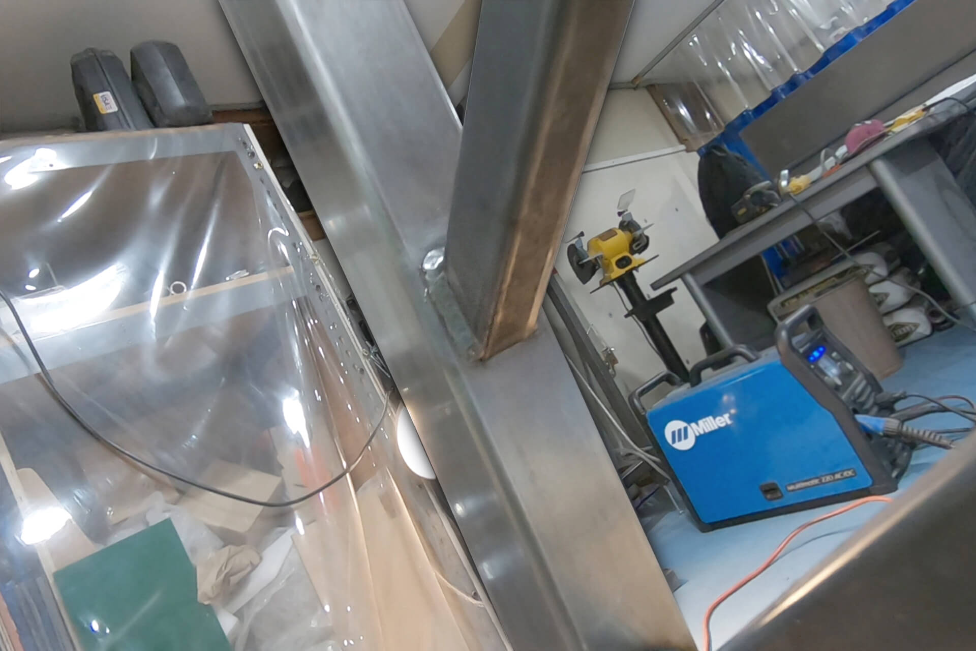
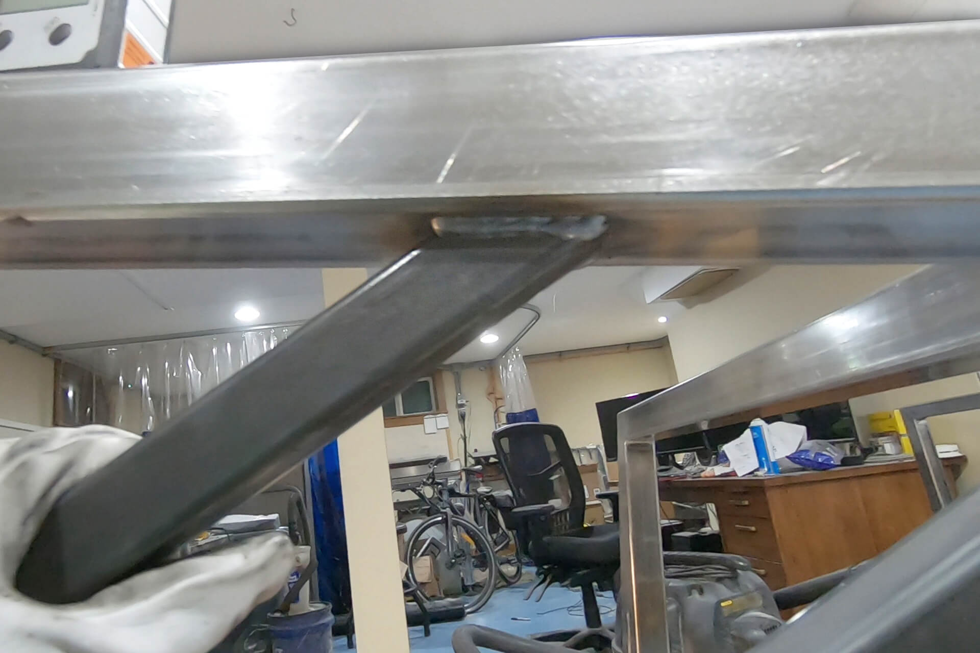
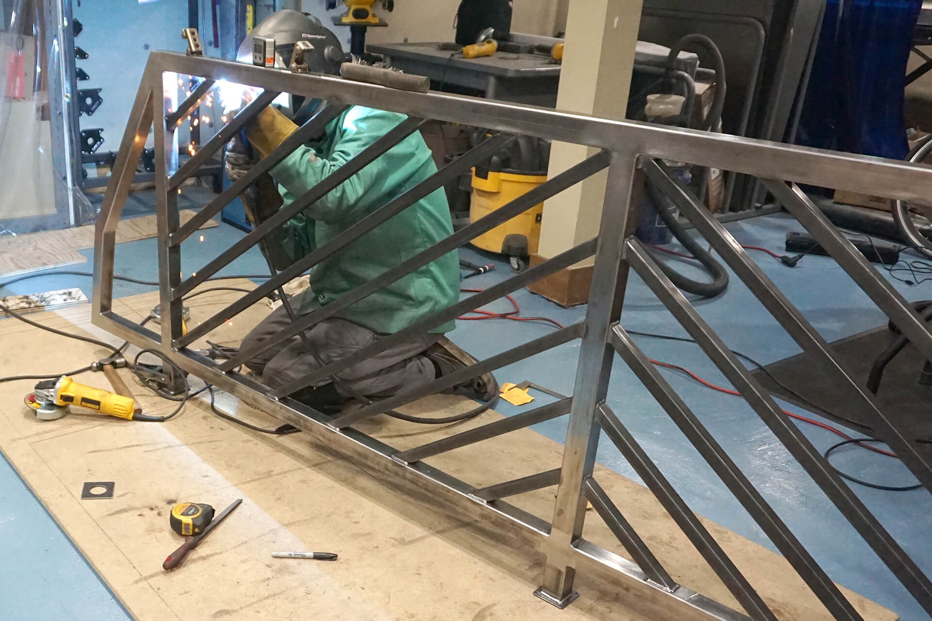
Tack weld the bottom frame of the larger railing. Use a large digital angle finder for accuracy. Test fit this piece to ensure it lines up with the dome’s upper floor railing trim.
Make adjustments if needed after test fitting, then fully weld the tacked connections once everything fits properly. Weld opposite sides sequentially to reduce heat warping.
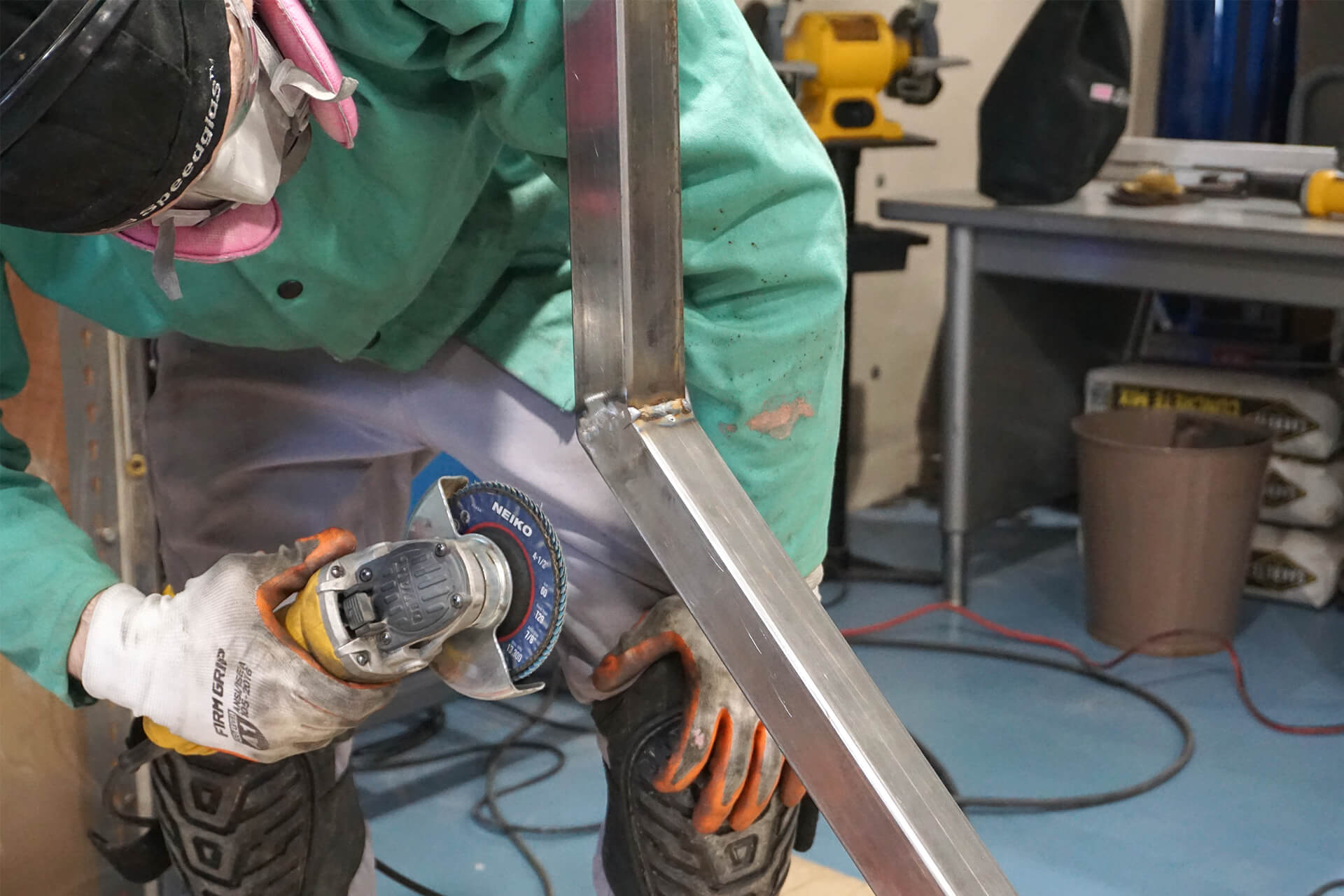
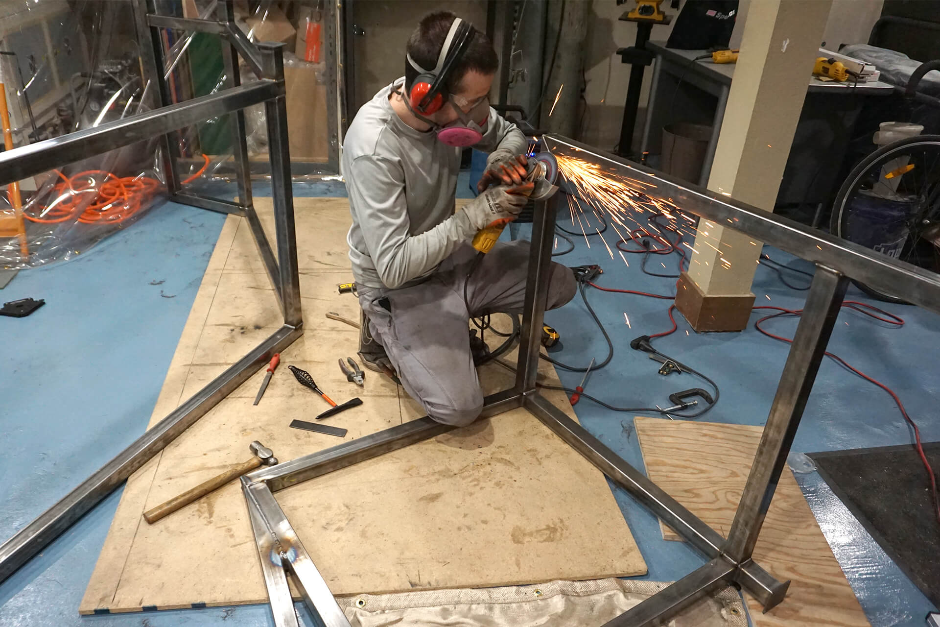
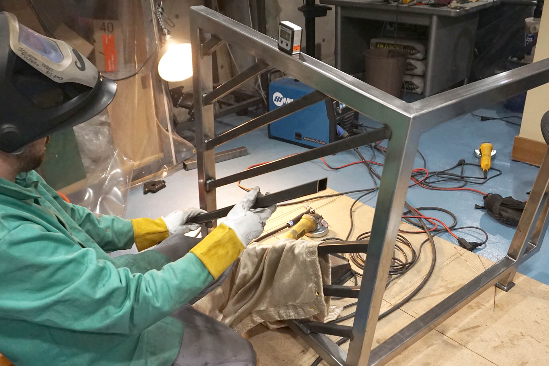
Use an angle grinder with a sanding disc to blend the welds flush with the square tubing.
Use the bottom frame as an alignment jig for tack welding the top frame. Then weld and blend it the same way as the bottom frame.
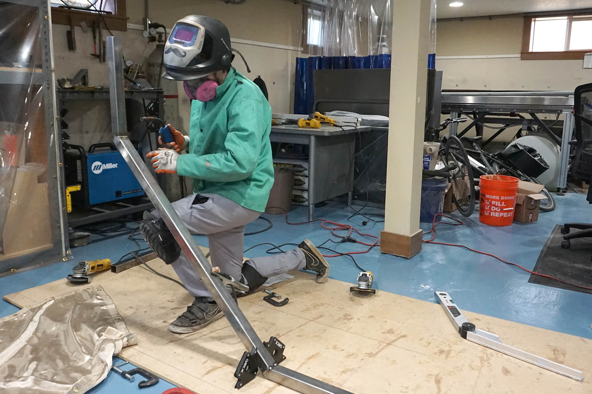
Clamp and tack weld the posts between the top and bottom frames.
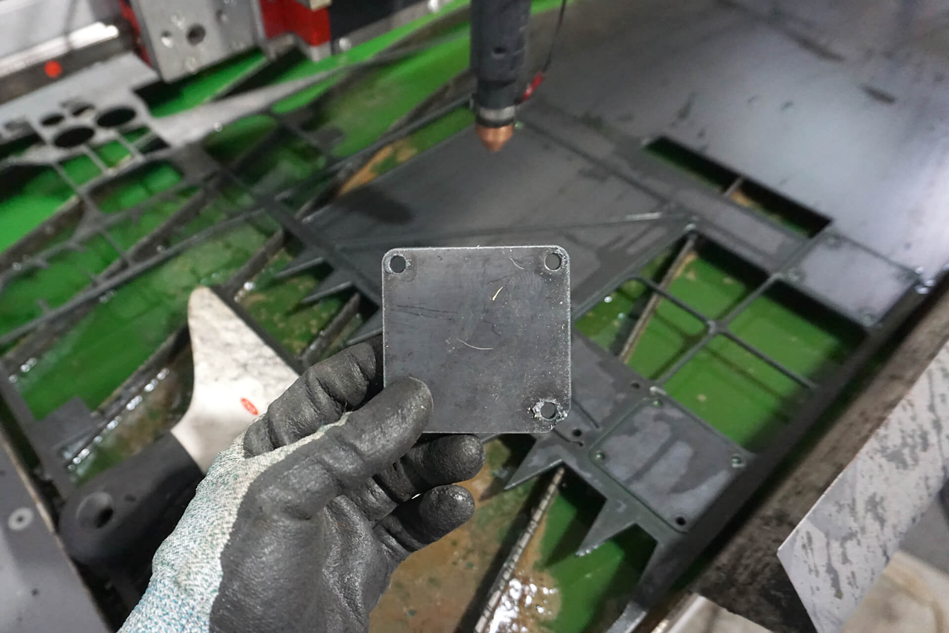
Fabricate the post feet from 10-gauge steel sheet. These will serve as attachment points, with each hole sized for a #10 wood screw. Shown is a post foot with one chamfered corner.
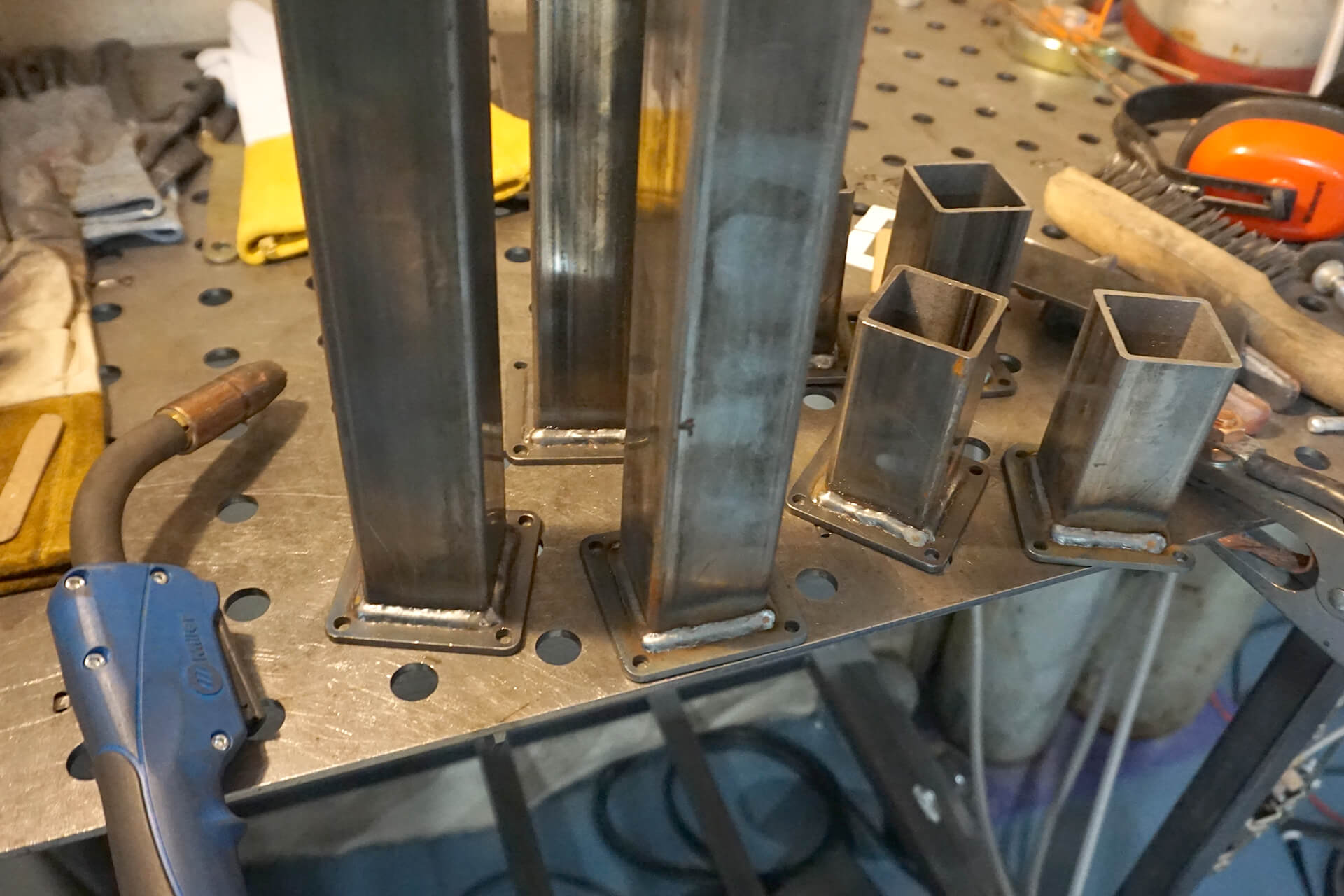
Weld the post feet to the posts.
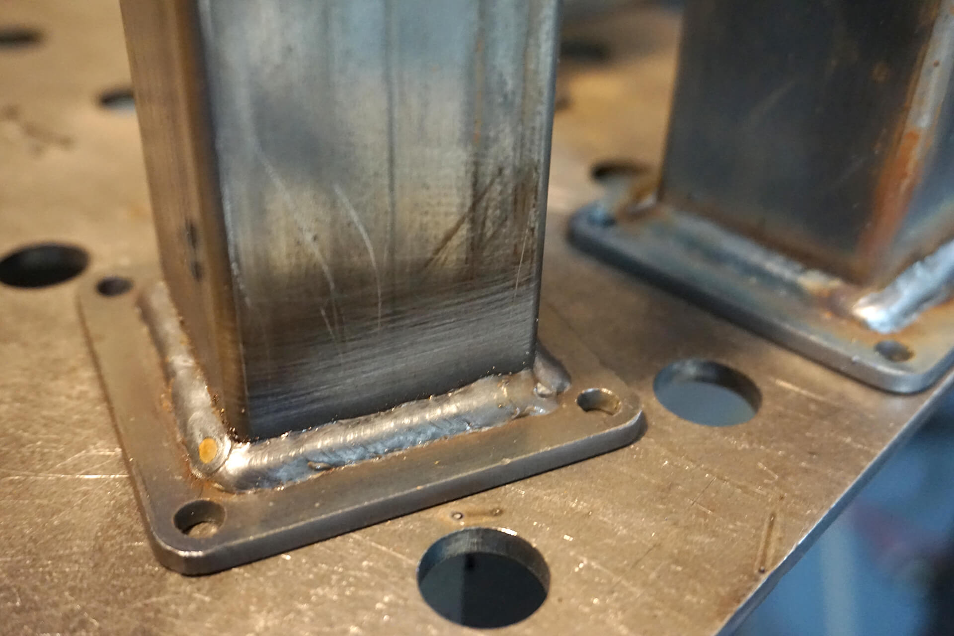
Inside-corner welds will not be ground, so they should look neat and be kept far enough from the holes for screw-head clearance.
Weld the posts to the frame, then finish welding the frame. Weld opposite sides sequentially to reduce heat warping.
Fabricate the smaller railing in the same fashion. Blend all outside-corner and butt-joint welds flush with the square tubing.
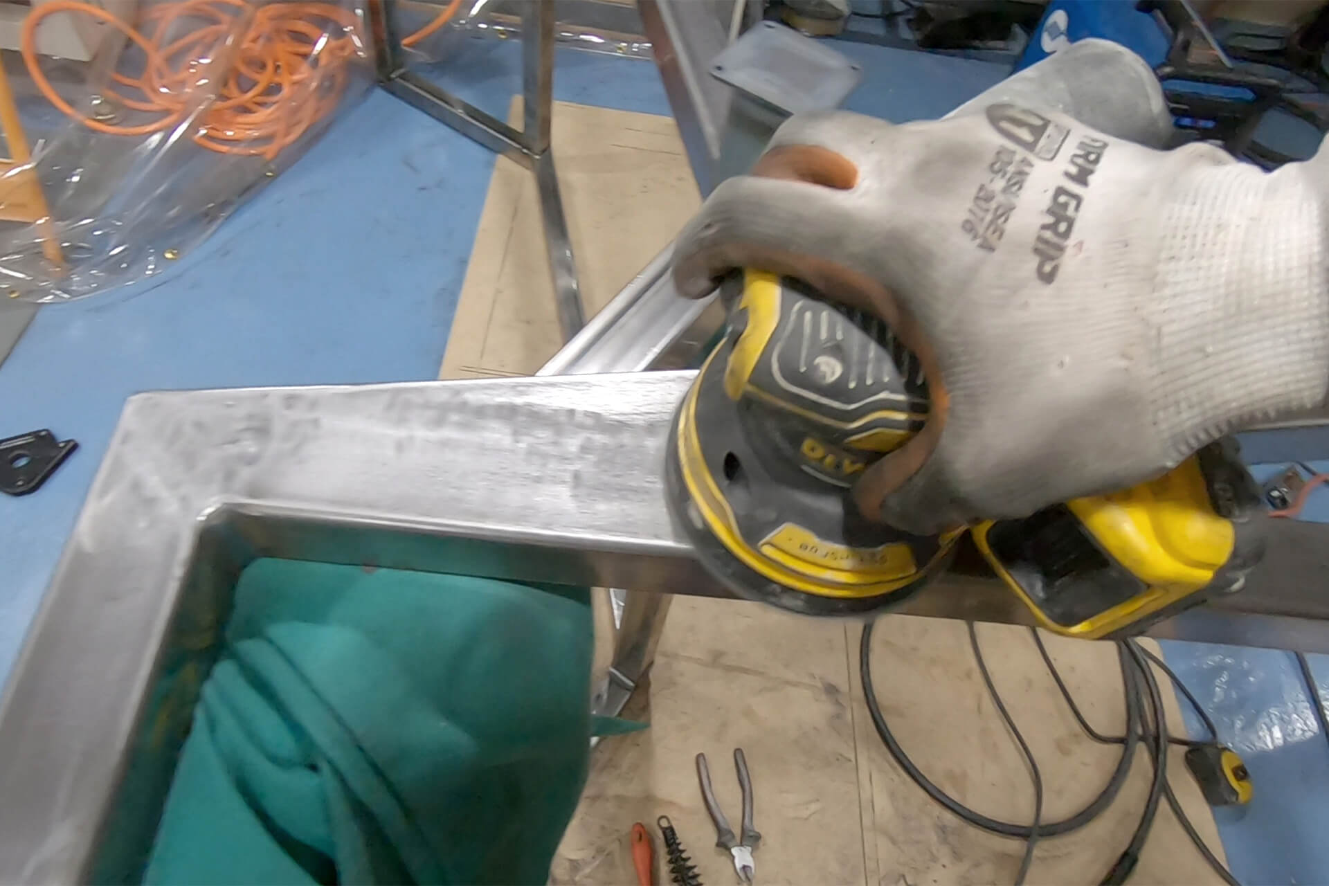
Use an orbital sander with 60-grit sandpaper for final blending.
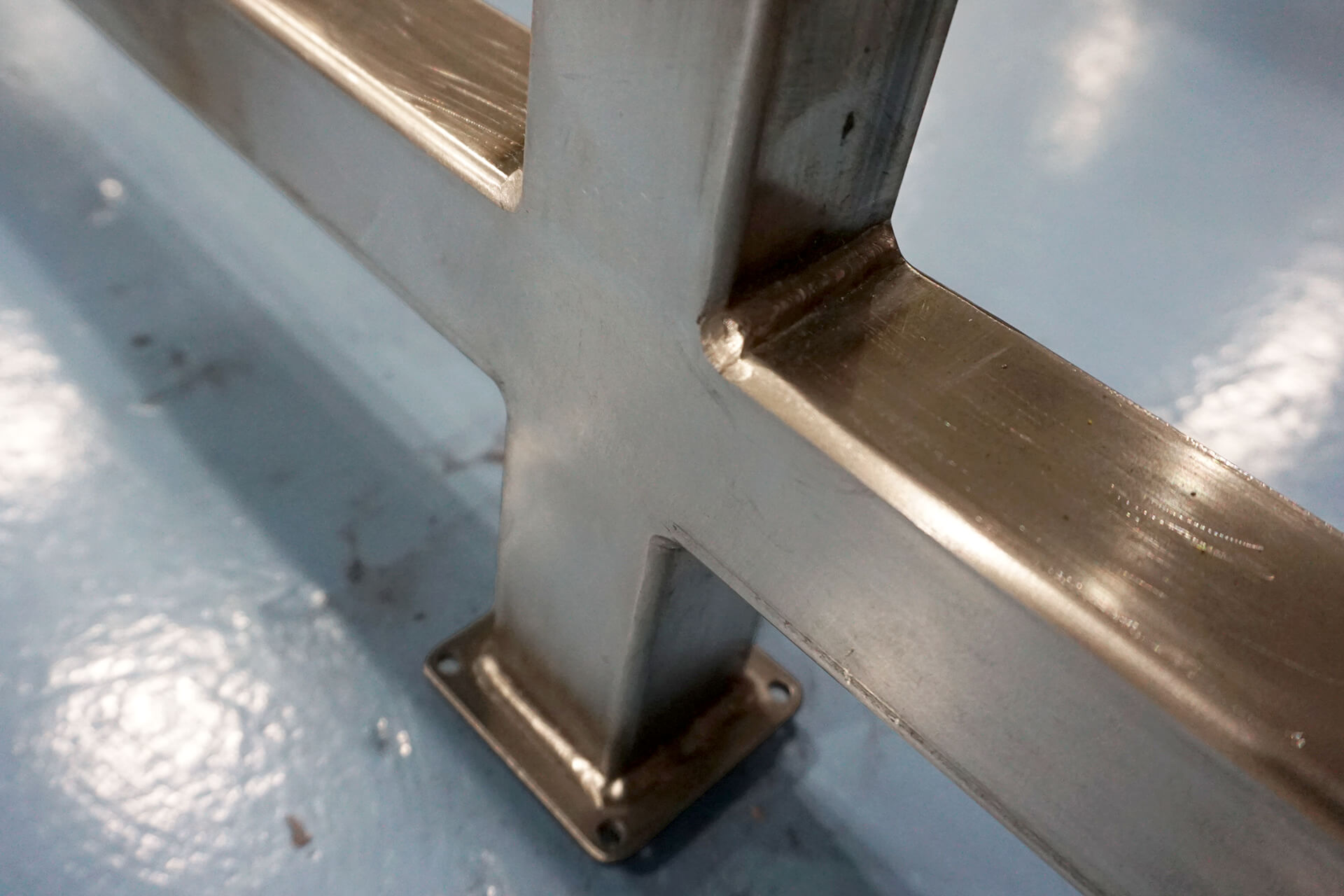
Detail shot showing a well-blended surface. Note: inside corners are cleaned of weld spatter but do not need grinding or blending.
Cut the baluster pieces for the smaller railing from 1.0” square steel tubing. Debur the cut ends with a file.
Position balusters with the aid of magnet tools and a digital angle gauge. Strong Hand Tools Magnetic V-Pad shown here. Note how cleanly the mitered cuts align with the frame.
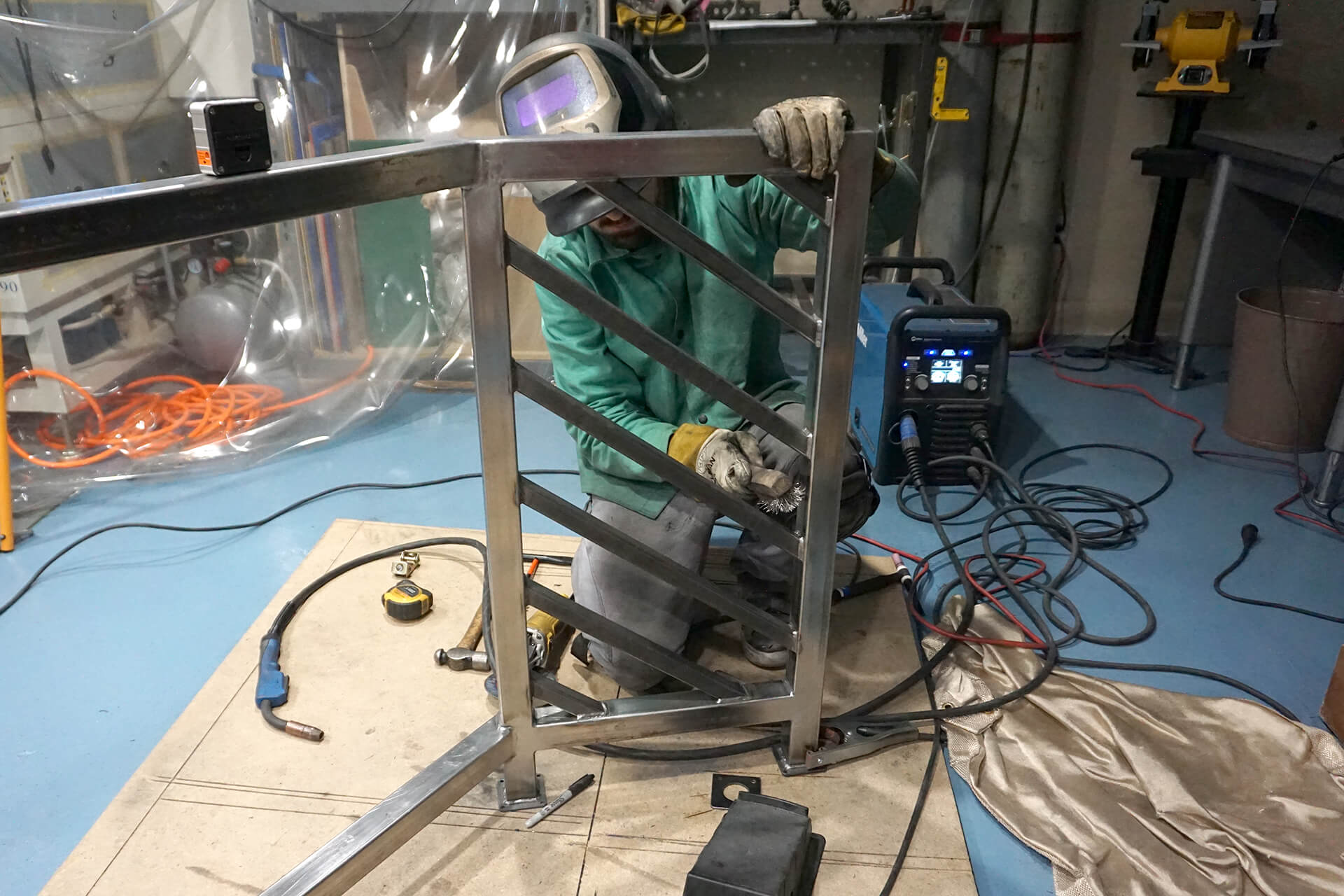
Weld each baluster to the frame. Use a welding blanket to protect lower surfaces from weld spatter.
Scrape off any weld spatter and use a wire brush to clean the welds.
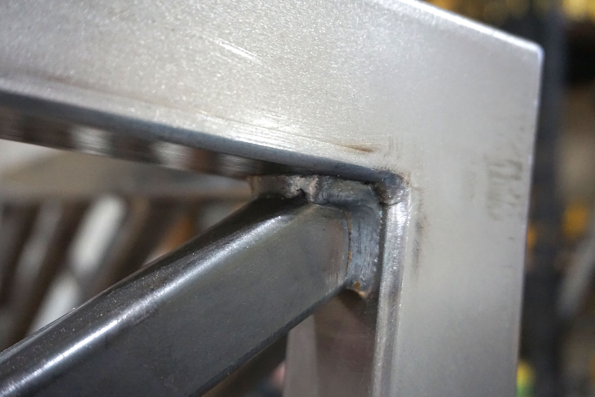
Detail shot showing a baluster welded into the corner of the frame. The bottom side (not visible) is left unwelded.
The baluster ends touching a frame post are welded on three sides, with the bottom side (not visible) left unwelded.
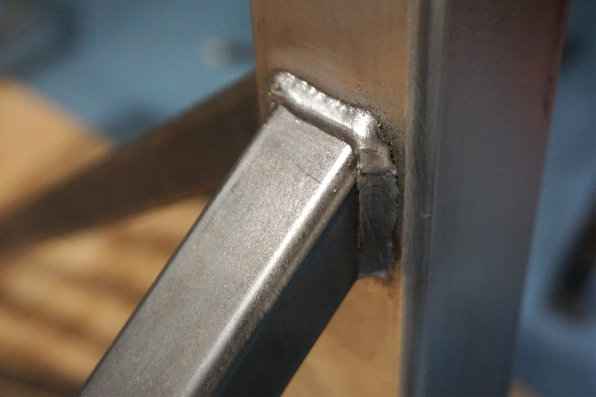
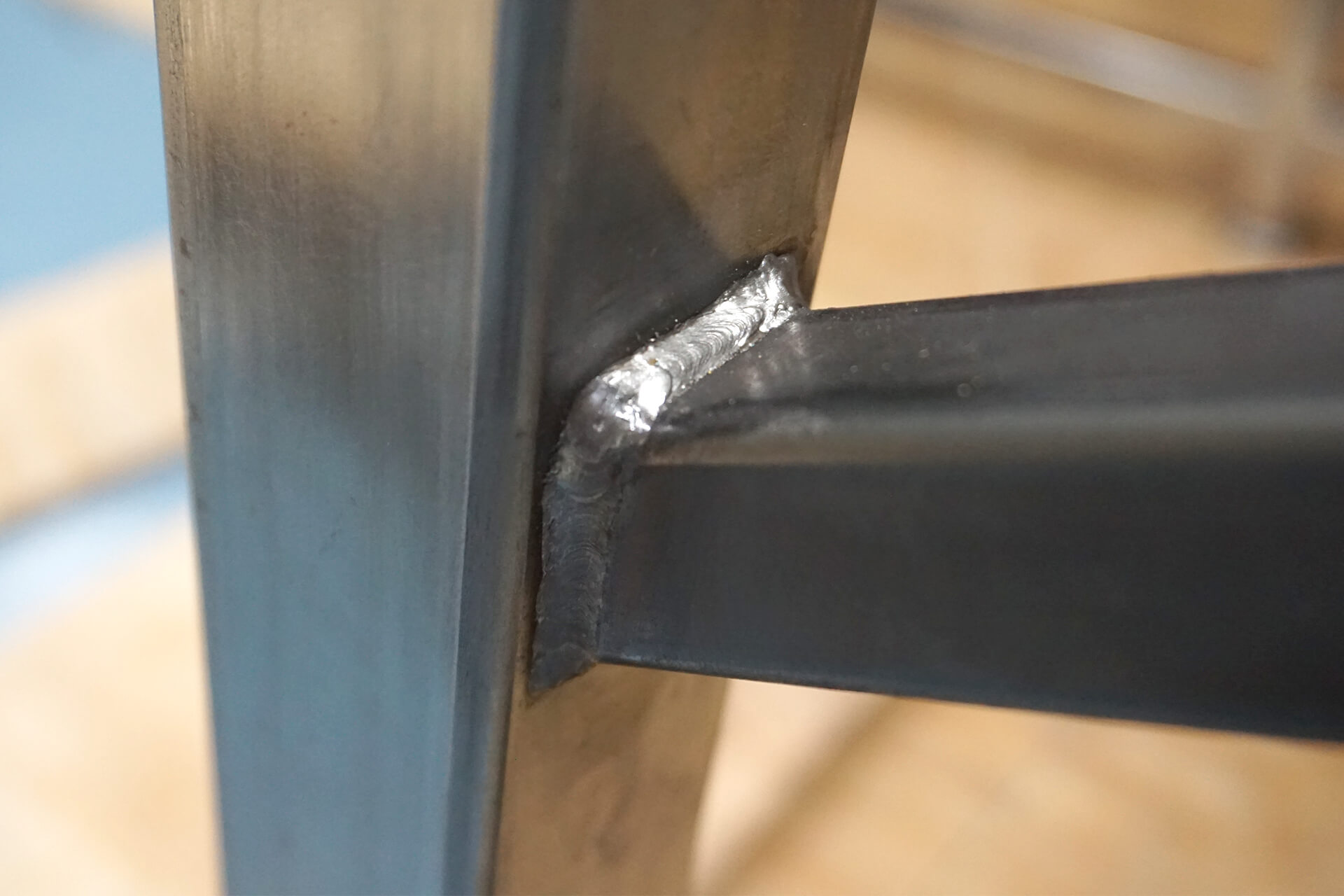
The upward-angled baluster ends are also welded on three sides.
Detail shot showing the unwelded bottom side of a baluster-to-post connection.
The baluster ends touching the top rail are welded on only two sides.
The completed smaller railing.
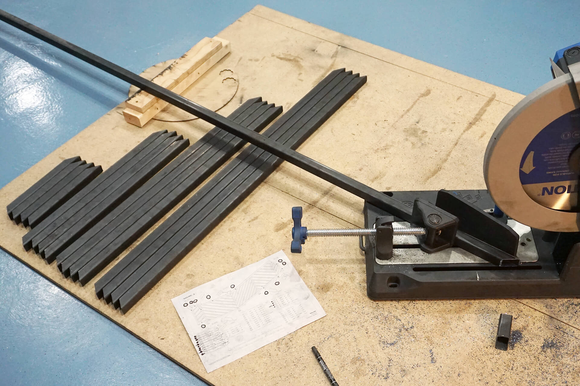
Cut the baluster pieces for the larger railing from 1.0” square steel tubing. Debur the cut ends with a file.
One panel of balusters requires a tricky compound angle cut. Create a jig to simulate a tilted cutting blade. With this questionable setup, the offcut is the desired piece.
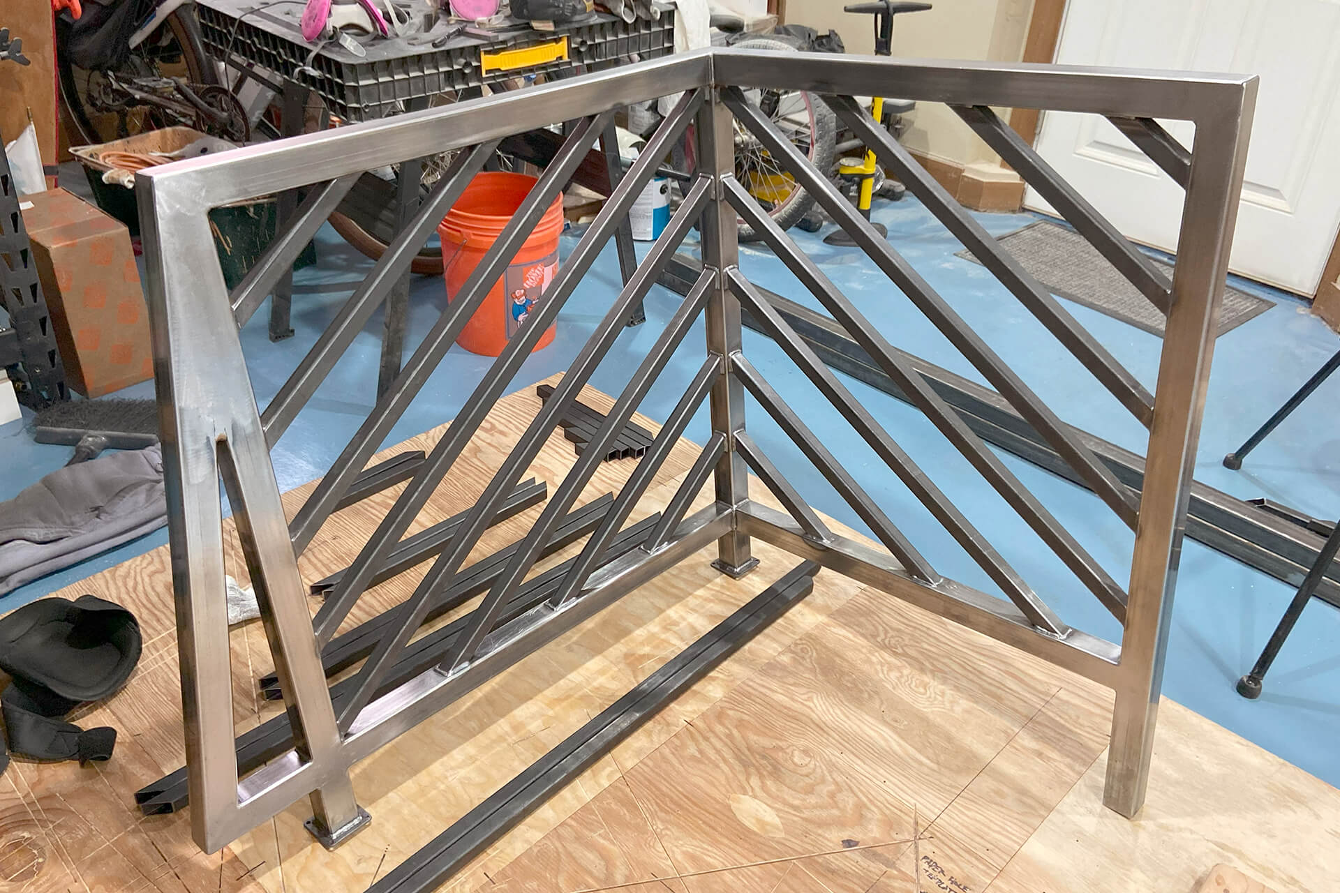
Weld the balusters into the two symmetrical long-panels.
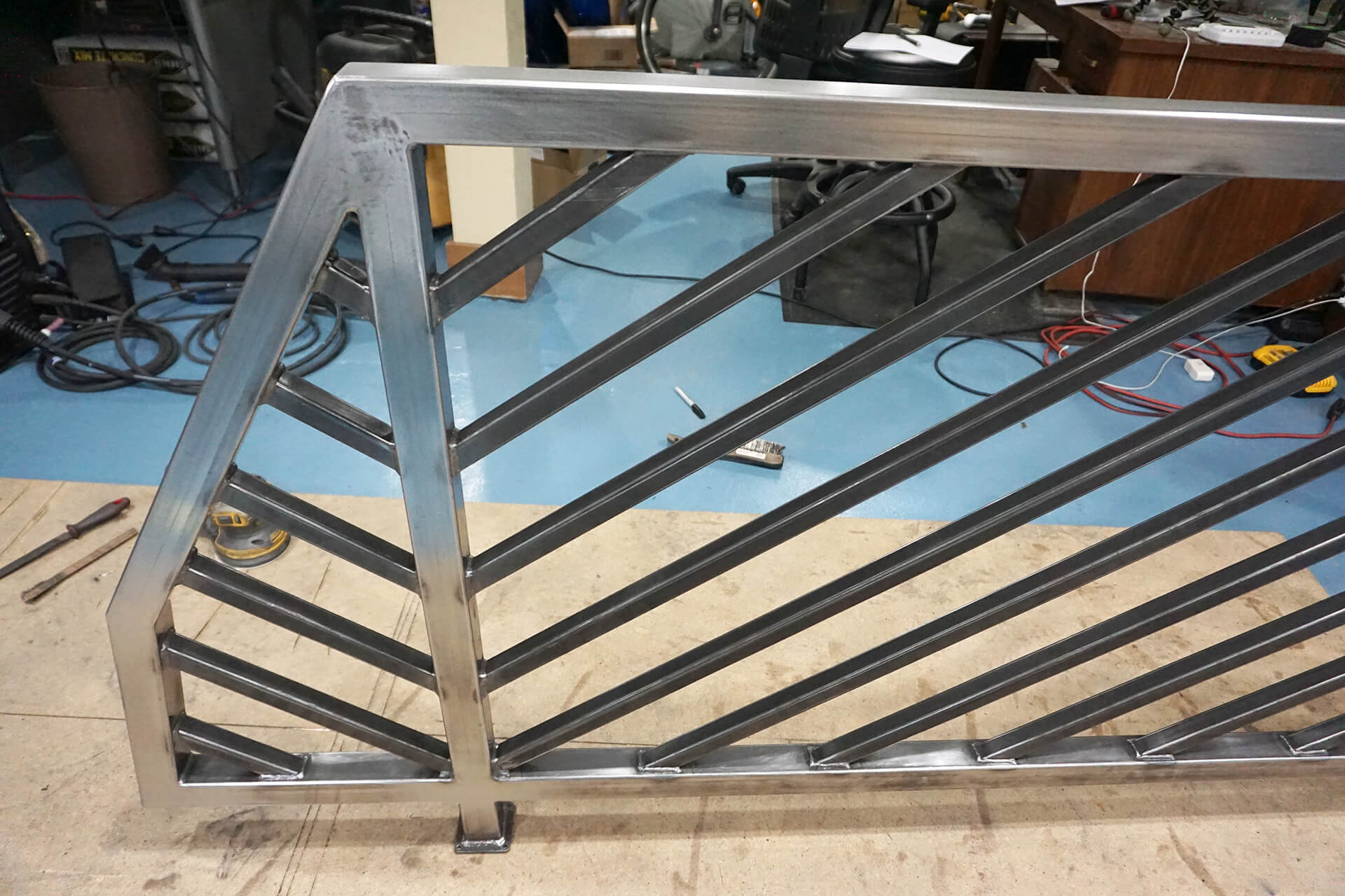
Weld the balusters into the small angled end panel.
Weld the balusters into the other end panel. Note: The two top and two bottom balusters are slightly different lengths.
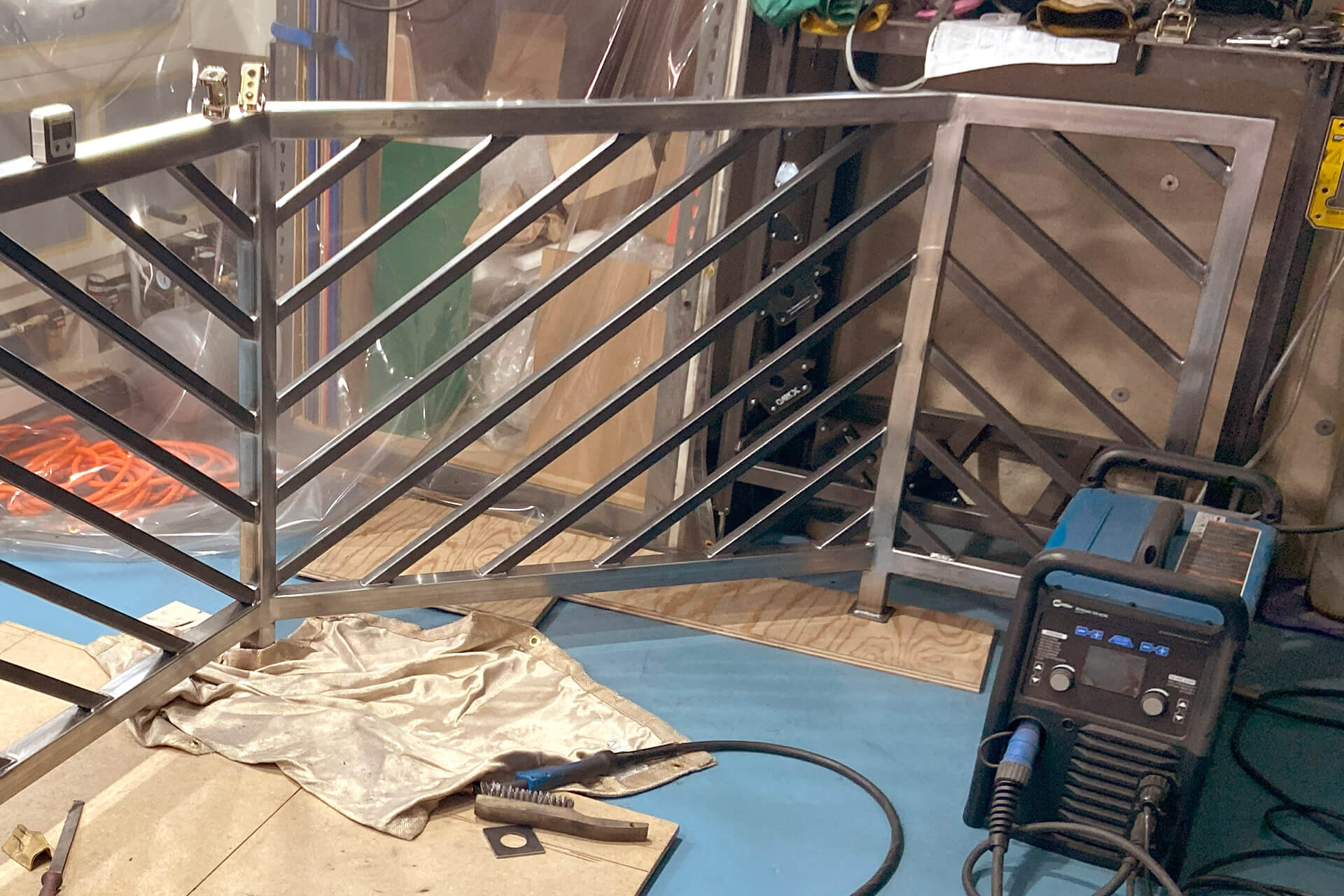
Weld the balusters with the compound angle cuts into the angled panel. All balusters should remain parallel to each other with the same spacing.
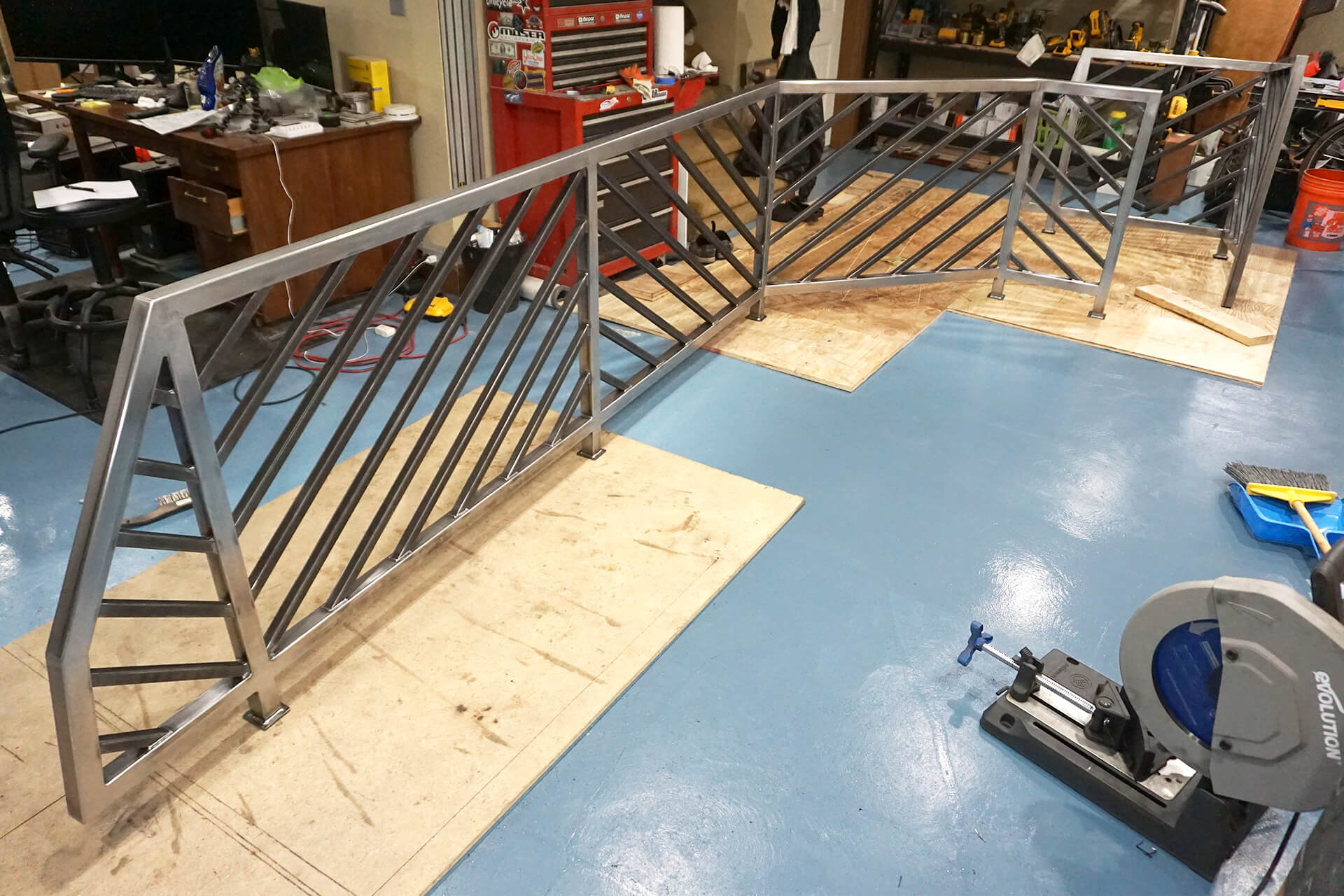
Congratulations on completing the railing fabrication! Ensure all surfaces are free of weld spatter, defects, rust, and oils before powder coating.
Next Step